1 minute read
Model 4700 Maintenance Manual
Section 7.Component Procedures
Drive and Brake Drive Unit/Motor Assemblies
18.Reassemble in reverse order of disassembly.
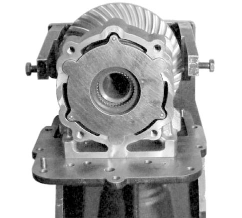
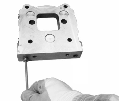
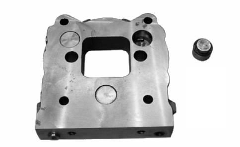
•torque the four brake cover mounting bolts to 50 ft. lb. (68 Nm). See Figure7-34.

•torque the two lower brake cover mounting bolts to 34 ft. lb. (46 Nm). See Figure7-33.

•torque the flange mounting bolts to 34ft. lb. (46 Nm). See Figure7-30.

•torque the reduction gear mounting bolts to 207ft. lb. (280 Nm). See Figure7-28.
19.Bleed service brake.
20.Remove truck from jack.
Publication 1160093, Issued: 20 May 2013 7-33
Section 7.Component Procedures
Model 4700 Maintenance Manual
Brake Pedal Adjustment Drive and Brake
Brake Pedal Adjustment
Pedal clearance should measure 1.6 in. (40 mm) from the floor when the pedal is in the neutral position.
132 lb. (60 kg) maximum pressure is required to fully depress the brake pedal.
Make sure that there is some clearance between the end of the brake pu sh rod and the master cylinder piston face. The push rod should float slightly in the piston as shown in Figure7-38
Figure 7-38.Brake Pedal Adjustment Points
132 lb. (60 kg)
1.6 in. (40 mm)
Publication 1160093, Issued: 20 May 2013


