1 minute read
Model 4700 Maintenance Manual
Section 7.Component Procedures
Drive and Brake Drive Unit/Motor Assemblies
3.Torque the four motor mounting bolts to 17 ft. lb. (23 Nm).
4.Reinstall the drive unit components in reverse order of removal.
5.Reinstall mast. See “Mast Removal and Installation” on page7-68.
6.Bleed brakes.
Brake Service - S/Ns below 10677
Replace the brake shoes when the braking material thickness is <0.08 in. (2 mm).
1.Park the lift truck on a level surface and engage the parking brake. Lower the carriage completely.
2.Turn the key switch OFF and disconnect the battery connector.
3.Block the steerable wheels to prevent truck movement.
Use extreme care whenever the truck is jacked up for any reason. Never block the truck between the telescopic and the floor. Use a suitable hoist to stabilize the mast. Keep hands and feet clear from beneath vehicle while jacking. Use jack stands or solid blocks to support truck. Do not rely on the jack alone. See “Jacking Safety” on page2-8.
4.Jack the front of the truck. Securely block the truck in position.
5.Remove the drive wheels.
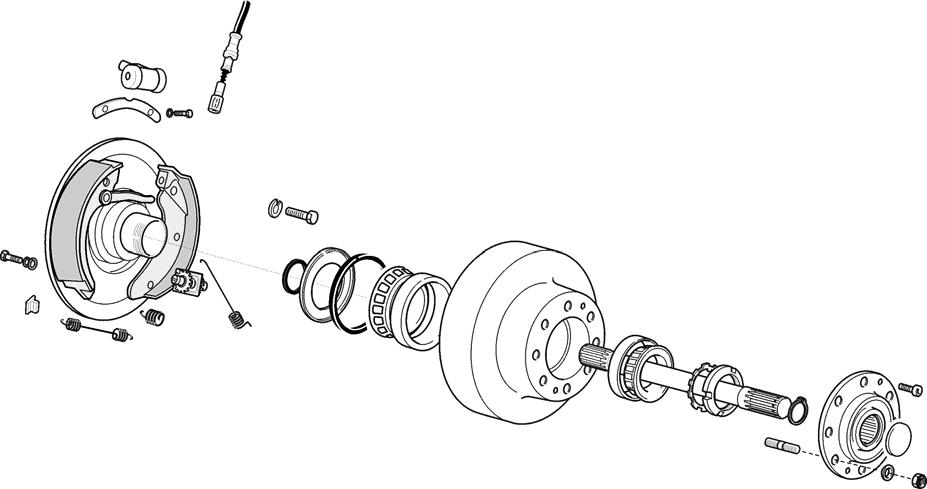
6.Remove the two hex head bolts securing the hub cover to the brake drum. See Figure7-25
7.Carefully remove the hub cover by driving a screwdriver between the hub cover and drum with a rubber hammer.
8.Wipe excess grease from the gear nut and safety ring. Disengag e safety ring tooth from nut and remove.
9.Remove the roller bearing and brake drum.
Publication 1160093, Issued: 20 May 2013
Section 7.Component Procedures
Model 4700 Maintenance Manual
Drive Unit/Motor Assemblies Drive and Brake
10.Remove old brake shoes and install new set.
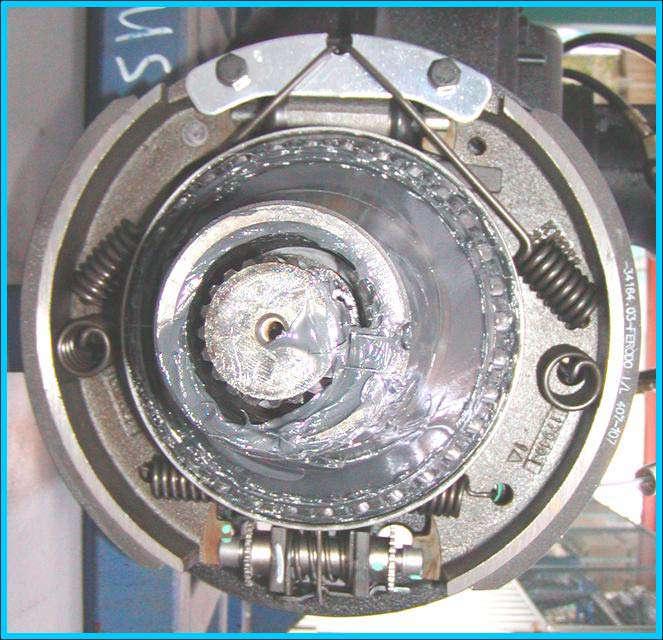
11.Set the automatic adjustment mechanism to allow clearance for the brake drum by turning the adjuster wheel clockwise. See Figure7-26 .

New brakes must be engaged several times before they become “seated” with the brake drum. Be careful when “breaking in” new brakes.
15.Drive the truck backward in an open ar ea and engage the brake pedal several times to set the automatic adjustment mechanism.
Brake Service - S/Ns 10677 and up
The braking system is made up of seven discs in an oil bath. Refer to Figure7-27
When the pedal brake is depressed, three pistons apply pressure to the outer fixed disc, compressing the disc group; six stationary discs and seven inner toothed rotating discs.

When the parking brake lever is engaged, pressure is applied to pins that mechanically apply pressure to the outer fixed disc, compressing the disc group.
12.Reassemble brake assembly in reverse order of disassembly.
13.Remove truck from jack.
14.Reconnect the battery connector and turn the key switch ON.
Publication 1160093, Issued: 20 May 2013


