Series 1000 and 1500 38.18. The red wire on the OCR plug carries battery voltage. •
Behavior: D.C. battery voltage should show-up on a volt meter when the red probe is touched to this terminal and the black probe is grounded, regardless of the key switch position.
•
Circuitry: This wire draws power directly from the B terminal on the key switch.
•
Interpretation: If there is not battery voltage at this terminal, the tractor is probably not function at all. Look for a blown fuse, disconnected battery, disconnected ammeter or some other major fault.
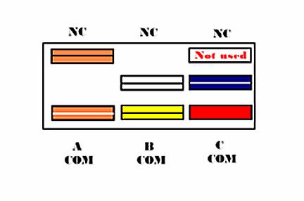
39.2. B-COM is in the safety shut-down circuit. It is a normally opened (NO) set of contacts. A circuit is completed from the M terminal on the key switch through the yellow wire to the Magneto terminal on the RMC module through the yellow wire with black trace when the contacts are closed. This gives the RMC module the ability to turn-off the engine when the PTO is ON. 39.3. In C-Com, power is supplied to the PTO switch from the A1 terminal of the ignition switch through a red wire.when the PTO switch is turned on this completes the circuit to allow power to go to the PTO clutch. It is a normally opened (NO) set of contacts.
38.19. The purple wire provides a ground signal to the RMC module when the key switch is placed in the REVERSE CAUTION MODE. •
Behavior: There should be continuity to ground at this terminal when the key switch is in the REVERSE CAUTION MODE position.
•
Circuitry: When the key switch is in the REVERSE CAUTION MODE position, a ground path is established by connecting terminal A2 to terminal L within the key switch. The white wire from the RMC module connects to A2, and a green ground wire connects to L.
•
Interpretation: If the purple wire fails to reach a ground path when the key switch is in the REVERSE CAUTION MODE position, the RMC module will not arm or operate. Check the key switch for continuity between A2 and L in the REVERSE CAUTION MODE position, confirm that the green wire connecting to the L terminal does have good continuity to ground, and check for any loss of continuity in the purple wire that extends from the key switch to the RMC module, including the molded connector between the two components.
•
If the RMC plug test indicates fault with any of the safety switches, the next step is to test the suspect switch.The operation of those switches is described in the following sections.
39.
UNDERSTANDING THE PTO SWITCH
Figure 39.3
NOTE: The top terminals are showing normally closed at rest and the middle terminals are normally open at rest NOTE: There are three contacts on the right side in the C-COM.For this application the normally opened (NO) contact is used.
39.1. A-COM is in the starter inhibit circuit. It is a normally closed (NC) set of contacts. When the PTO is OFF, and the contacts are closed, power coming from the brake switch (key switch in START, brakes ON) through the orange wire with black trace is passed on to the trigger terminal on the starter solenoid through the orange wire with white trace.
77

