15 minute read
38. ELECTRICAL SYSTEM


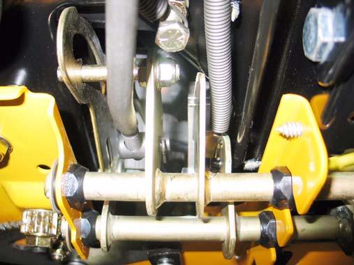
37.14.Remove the large hex flange nuts securing the axles to the pivot bar. 37.15.Remove the front axles and tire assemblies from the pivot bar. 37.16.Remove the pivot bar stop bolts and hex nuts using a 3/4" socket and a 9/16" wrench. NOTE: On units with the J-bolt style deck stabilizer rod. the mounting plate will come off with the pivot bar stop bolts. 37.17.Squeeze in on the wiring harness locking tab at the right muffler bracket and release the wiring harness using needle nose pliers. 37.18.Remove the hex screws securing the left and right muffler support brackets to the frame using a 1/2" socket. See Figure 37.18.
Muffler Support Brackets
Hex Screws
Pivot Bar Stop Bolt
Figure 37.18
37.19.Remove the left and right muffler support brackets.
CAUTION: On newer production units the muffler support brackets cover the front pivot axle bracket. when you remove the muffler support brackets take care to prevent the pivot axle from falling off.
NOTE: The brackets are marked for correct installation. 37.20.Remove both self tapping screws securing the front pivot axle bracket to the frame using a 1/2" socket. See Figure 37.20.
Screws
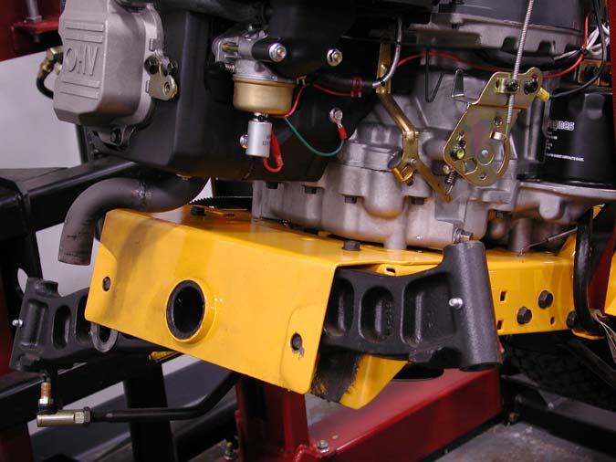
Front Pivot Axle Bracket
Figure 37.20
37.21.Remove the front pivot axle bracket. 37.22.Reassemble in reverse order.
38. ELECTRICAL SYSTEM
38.1.
Introduction: The electrical system for the 1000 and 1500 series tractors can be classified into three categories: • RMC
• Pre-RMC
38.2. The RMC module contains electronic logic circuits. When diagnosing anything that is con nected to the RMC module, high impedance test light or a high impedance digital volt-ohm meter (DVOM) should be used. The amperage draw of a standard incandescent test light may over-bur den some internal electronic circuits, burning-out the module.
NOTE: These tools are not outrageously expensive or exotic. High impedance test lights (Thexton model 125 is typical) can be purchased locally from stores like NAPA for under $30.00. Appropriate multi meters can be purchased for under $100.00, and are an invaluable tool for any competent technician. • It is typical when industries shift from electromechanical to electronic controls that diagnosis shifts from tracing through a number of independent circuits to checking the in-puts to and out-puts from a central processor. This is similar
to, but much less complex than the transition that the auto industry made with the conversion to fuel injection in the 1980s. • The starter safety circuit has no connection to the RMC module.
• The safety circuits that are capable of turning-off the engine work through the RMC module.
• It is still important to be familiar with the workings of the individual components of the electrical system, but some of them can now be checked from a central point on the tractor. This makes life easier on the technician, frequently making it unnecessary to connect to difficult to reach switches in the preliminary stages of diagnosis.
• The function of individual safety switches can be seen as providing information “inputs” to the RMC module.
• The next part of this section gives a detailed description of the electrical components on this tractor, their function in the system, and their physical location on the tractor. Armed with this information and the proper tools, a technician should be able to efficiently diagnose most electrical problems.
NOTE: The test procedures for the normal mode in the RMC system are the same as the PreRMC system and will not be called out sepa rately in this manual. 38.3. The Key Switch is similar to those used in a variety of MTD applications since 1999. The dif ference in this case is that it is incorporated in the same housing as the RMC module; the two items are not available separately. See Figure 38.3.
RMC module
Key switch
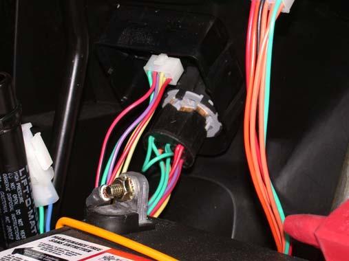
Figure 38.3
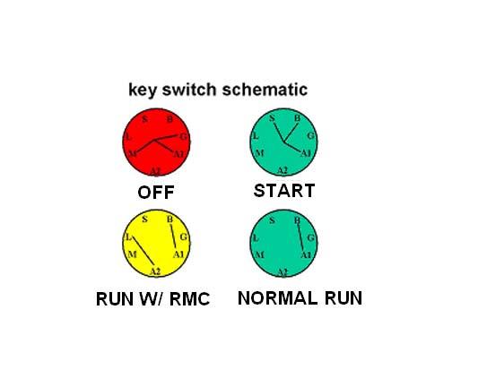
38.4. In the OFF position, continuity can be found between the M, G, and A1 terminals. See Figure 38.4.
Figure 38.4
• M is connected to the magneto by a yellow wire, G is connected to ground by a green wire, and A1 is connected to the after fire solenoid and alternator.
• In the OFF position, the magneto primary windings are grounded, disabling the ignition system. The alternator output that normally keeps the after fire solenoid powered-up is given a more direct path to ground, depriving the after fire solenoid of power. This turns-off the fuel supply.
Symptom-engine runs with key in OFF position : The key switch is not completing the path to ground either because of an internal fault or a bad ground connection elsewhere in the harness. Check continuity between M, G, and A1 terminals with key switch in OFF position. Check green wire continuity to ground. • Symptom-loud “BANG” when key is turned to the OFF position: The after-fire solenoid is not closing, either because it is physically damaged or the alternator output is not getting grounded. Check for power at the solenoid. Check continuity between G and A1 terminals. Check continuity from red wire to afterlife solenoid. • Symptom-Engine runs 3-5 seconds after key is turned to OFF position: The after-fire solenoid is turning-off the fuel supply, but the ignition is continuing to operate. Check continuity between the M and G terminals in the OFF position. Check continuity from yellow wire connection all the way to the spade terminal on the magneto. 38.5. In the START position, continuity can be found between B, S, and A1 terminals. • Battery power from the B terminal is directed to the start circuit through the S terminal and to the afterlife solenoid through A1. There is no alternator output to A1 until the engine is running. Symptom-No crank and no starter solenoid click: Power is not getting to the trigger spade on the starter solenoid. Test for a good battery then check for power where the fused red wire with white trace connects to the B terminal. Check for continuity between B and S terminals in START position. If power is getting to the S terminal in the START position, the problem lies down-stream in the starter circuit; Check continuity from the orange wire on the S terminal to the orange wire with white trace on the trigger spade on the starter solenoid. If it is broken, trace through the brake and PTO switches.
Symptom-No crank, solenoid click : The problem lies in the heavy-gauge side of the starter circuit; battery cables, starter cable, solenoid, or ground issue.
Symptom-Crank, spark, but not fuel : First test for power at the solenoid, if no power the check for continuity from B to A1 in the START position. If power is reaching the red wire that connects to the A1 terminal in the start position, the problem lies down-stream of the key switch. A handy quick-check is to apply power to the red wires where they connect to the S terminal (whole circuit) or directly to the afterlife solenoid to listen for the audible “click” that it makes when functioning. Symptom-Crank, but no spark : This is a highly unlikely scenario. If it occurs after a key switch has been changed independently of the RMC module, this would arouse suspicion that the wrong key switch was installed. Otherwise, the problem lies elsewhere in the safety circuits or engine. Do not over-look the possibility of a bad magneto or chafed ground lead within the engine harness. 38.6. In the NORMAL RUN position (green zone), the B and A1 terminals should have continuity. Once the engine is running, the alternator produces current that tracks-back from the A1 circuit to charge the battery, via the red wire with white trace connected to the B terminal. The plain red wire carrying alternator current to the A1 terminal doubles-back, with the second plain red wire on that terminal supplying power directly to the after fire solenoid. Symptom-Battery does not charge: If the switch has continuity between B and A1 in the RUN position, follow the engine manufacturer’s recommendations for testing alternator output. If alternator output is getting to and through the key switch, but not reaching the battery, the fuse may have blown after start-up. A blown fuse will disable the starter circuit. A simple quick-test for the presence of alternator output at the battery is to check across the battery posts for DC voltage. Symptom-After fire solenoid does not work: engine starts and dies: The after fire solenoid is powered directly by the red wire carrying alternator output, and should operate independently of anything else on the tractor once the engine is running. If the alternator fails and battery power is not reaching the afterlife solenoid through the key switch, it will not work. This is an unusual set of circumstances.
38.7. In the REVERSE CAUTION MODE (yellow zone), the same characteristics are true as for the normal run position, but in addition the L ter minal will have continuity with the A2 terminal. The A2 terminal is connected to the RMC mod ule by a white wire. The L terminal (formerly used for the lighting circuit) connects directly to the ground circuit of green wires. When the key is in the REVERSE CAUTION
MODE position, the white wire carries a ground signal to the RMC module. When the parking brake is not set, this ground signal tells arms (enables), but does not turn-on the RMC mod ule.
Symptom-RMC module will not turn-on: Check for continuity between A2 and L terminals on the key switch when it is in the REVERSE CAUTION MODE position. Confirm that the green wire has continuity to ground. If the switch is capable of establishing a ground signal to the RMC module, the problem is likely to lie elsewhere in the system.
Symptom-RMC module will not turn-on : confirm that the ground path (continuity to ground) to the white wire is broken when the key switch is in any position other than REVERSE CAUTION MODE. The RMC module is disarmed (disabled) when the parking brake is set. To re-arm the module, the key is moved to another position, breaking the ground signal, then returned to the REVERSE CAUTION MODE, re-establishing the ground signal. It works something like a latched relay. If it is not possible to break the ground-path, it is not possible to freshly establish it either, and the RMC module will not be armable. Causes for such a condition might include a shorted or incorrect key switch, or a chafed white wire shorting to ground between the key switch and the RMC module. 38.8. The RMC Module is in the same housing as the key switch, and is not available separately. For the purpose of diagnosis it is treated separately. Diagnosis in unit with the key switch introduces too many over-lapping variables. See Figure 38.8.
RMC module
Figure 38.8
38.9.
Principle: To diagnose the module, the simplest approach is to check all of the inputs (safety cir cuits) that are connected to it. If the inputs work properly, but the RMC module does not work properly (outputs), then the module can be determined to be faulty. A specific procedure is covered, following the description of the correct operation of the RMC module. 38.10. Working properly: The module cannot be diagnosed if its function is not understood. It is designed to work as follows: See Figure 38.10.
Indicator
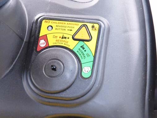
Figure 38.10
• When the RMC module is disarmed, the tractor will operate as MTD tractors have historical operated: If reverse is engaged when the electric PTO is ON, the PTO clutch will turn-off. If the operator leaves the seat with the engine running, the engine will turn-off. If the operator leaves the seat with the PTO in the OFF position, the engine will turn-off unless the brake is applied. When the RMC module is armed, the tractor will operate identically to when the module is disarmed.
When the RMC module is armed and turnedon: The tractor will operate identically to when the module is disarmed, except that the operator will be able to put the transmission in reverse with the PTO engaged and the cutting deck will continue to run The operator may put the tractor into and out of reverse as many times as they wish without having to re-arm or turn-on the module again. To arm the RMC module: the operator must turn the key switch to the REVERSE CAUTION MODE (yellow zone), with the parking brake released.
To turn the RMC module ON: The module must first be armed, then the orange triangular button is depressed, illuminating the red LED indicator to indicate that it is ON. It is important that the operator must take two actions to turn the RMC module ON so that they do not do so inadvertently. The RMC module will turn-OFF and disarm if: The operator moves the key to any position other than REVERSE CAUTION MODE. The operator sets the parking brake. If the operator leaves the seat without setting the parking brake, the engine will turn-off. The key movement necessary to re-start the engine will make it necessary to re-arm and turn-on the RMC module if the operator wishes to continue with the ability put the tractor in reverse while the PTO is running. To re-arm and turn the module ON: If the key is in REVERSE CAUTION MODE position, it must be turned to another position (Normal Run), then returned to REVERSE CAUTION MODE. Once re-armed, the module can be turned-on by pressing orange triangular button. It will be confirmed that the module is ON by the illumination of the red LED on the module. 38.11. To identify a faulty RMC module: If the RMC module does not function as described, the RMC plug test should be the first step in diagnosis. • If the RMC plug test confirms that the safety circuits (inputs) work as designed, yet the RMC module does not work properly, the RMC module is faulty. • The RMC plug test will give an indication of what the problem is if it is not a faulty RMC module. If the problem is identified in a particular circuit, check the safety switch that is associated with that circuit. If the switch is good, then the problem lies within the wiring harness. NOTE: Like the electronic components found on most cars, the RMC module requires a fully charged battery to work properly. If the system voltage falls below 12 V. an accurate diagnosis of the RMC module is impossible because the module will be temporarily disabled by low volt age.

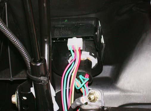
38.12.Disconnect the molded 8-pin plug from the RMC module. See Figure 38.12.
Figure 38.12
NOTE: For the 1000 series it may be necessary to unfasten the fuel tank and move it aside for easier access to the plug. For the 1500 series you may need to move the battery to get at the plug.
38.13.Looking at the plug head-on, it will be configured as shown in the diagram: There will be 8 female pin terminals. When probed they should yield the results described in the following sections. See Figure 38.13.
Figure 38.13
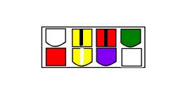
NOTE: You will see a difference in the configuration of the adaptor of the manual PTO vs. the Electric PTO.
38.14.Top left middle ❑-shape: Yellow wire with Black trace:
• Behavior: Should show DC power with the key on.
• Circuitry: The yellow wire with black leads directly to the PTO switch. 38.15.Check the PTO and seat safety circuits with the 8-pin pigtail connector unplugged, then recon nect it and continue with the RMC plug test. Behavior: When the female pin terminal leading into the main harness is probed (yellow wire), there should be continuity to ground only when the seat is empty. Circuitry: The yellow wire with white trace leads to the forward terminal on the seat safety switch, where it finds a path to ground when the seat is empty. Interpretation: If behavior is correct, the seat safety circuit is good. If there is continuity to ground when the seat is occupied, the switch may be inoperative, or there may be a short to ground in the wire leading to it. If there is not continuity to ground when the seat is empty, the switch may be inoperative or there may be an open condition in the wire leading to it. Circuitry: The yellow wire with black trace leads to the PTO switch, where it finds a path to ground when the PTO is ON. Interpretation: If behavior is correct, the N.C. side of the PTO switch /circuit is functioning properly. If there is continuity to ground when the PTO is OFF, the switch may be inoperative or there may be a short to ground in the wire leading to it. If there is not continuity to ground when the PTO switch is ON, the PTO switch may be inoperative, or there may be an open condition in the wire that leads to it.
38.16.There is a red wire with black trace between yellow wire with a black trace and the green wire. This wire provides the module with input from the reverse switch.
Behavior: When the tractor is in reverse, this terminal should have continuity to ground. Circuitry: This wire runs directly to the reverse safety switch on the transmission support for the CVT tractors or at the brake caliper on the hydros. This is a simple metal tang switch that grounds-out against the transmission control lever.
Interpretation: Continuity to ground when the tractor is not in reverse would indicate a short to ground north circuit. This could take the form of a chafed wire contacting ground, a bent reverse safety switch that is always in contact with another metal part, or a broken plastic insulator that separates the switch from the fender. Lack of continuity to ground would indicate a broken or disconnected wire leading to the reverse safety switch, or a switch that is not closing because of physical damage or corrosion. 38.17.At the opposite end of the top row from the yellow wire with black trace is a green wire. Behavior: The green wire should always have continuity to ground. Circuitry: The green wire leads to ground. Interpretation: If this ground path is not good, there will probably be other ground-related issues with the tractor: slow starter motor, slow battery charge, dim lights. All ground connections should be mechanically secure and corrosion free.