
2 minute read
15. DASH PANEL REMOVAL


• For the U-bolt style:
14.11. Loosen both lock nuts securing the adjustment nuts on the front of the deck stabilizer bracket using a two 3/4” wrenches.
Lock Nuts
Adjustment Nuts
Figure 14.11
14.12.Locate both adjustment nuts on the front side of the deck stabilizer bracket. See Figure 14.11. 14.13.Tighten both nuts to raise the front of the deck or loosen both nuts to lower the front of the deck using a 3/4” wrench. NOTE: Make sure you count the number of turns you put on the first nut and put the same number on the second nut. both nuts must be moved equally. 14.14.Retighten both lock nuts to jam the adjustment nuts into position when the proper adjustment has been achieved.
• For the J-bolt Style:
14.15.The J-bolt style stabilizer is adjusted in a similar fashion. Loosen the single lock nut away from the adjustment nut using two 3/4” wrenches.
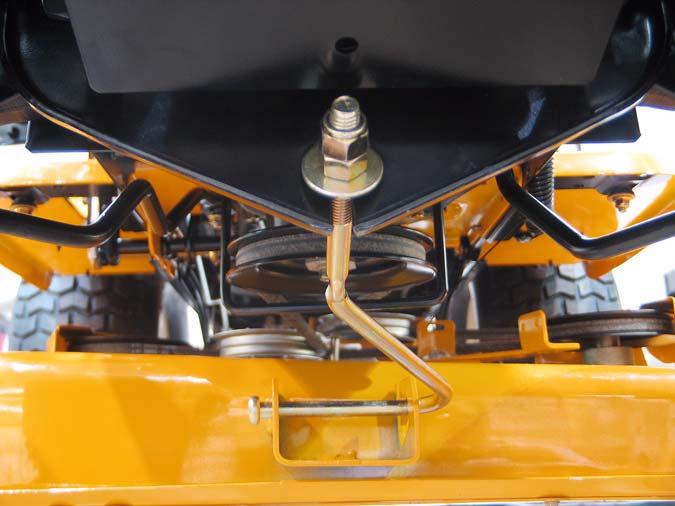
Lock Nut Adjustment Nut
Figure 14.15
14.16.To lower the front of the deck loosen the adjustment nut on the J-bolt. To raise the front of the deck tighten the lock nut. Tighten the lock nut against the adjustment nut when finished.
15. DASH PANEL REMOVAL
15.1. Remove fender, as described in the FENDER REMOVAL section of this manual.
15.2. For the 1500 remove the hood and battery, as described in the HOOD REMOVAL section of this manual.
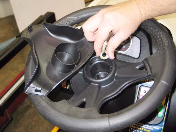
• For the 1000 remove the fuel tank by first removing the fuel cap. place a piece of plastic over fuel tank opening and put fuel cap back on. • Remove the four 1/2” screws holding the fuel tank in place. • Lift the fuel tank and place on top of engine or clamp the fuel line and remove it from the fuel pump and remove fuel tank from unit. 15.3. Pry the cap off the center of the steering wheel.
15.4. Remove the steering wheel from the steering shaft using a 1/2” wrench. See Figure 15.4.
Figure 15.4
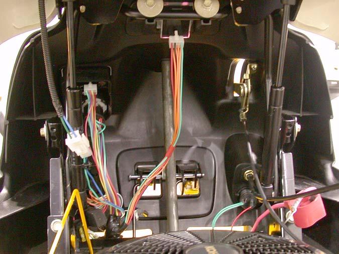
15.5. Disconnect the following dash-mounted electrical devices by unplugging the molded connectors: See Figure 15.5. Molded connectors
Figure 15.5
NOTE: Image shows 1500 dash. 1000 series dash components are in a similar location. • Key switch and OCR module • PTO Switch • Hour meter / Monitor • Accessory power port - if present.
15.6. Disconnect the rods that connect the Park Brake and Cruise Control mechanisms to the levers on the dash that control those features by removing the hairpin clips. See Figure 15.6.

Hairpin clips
Figure 15.6
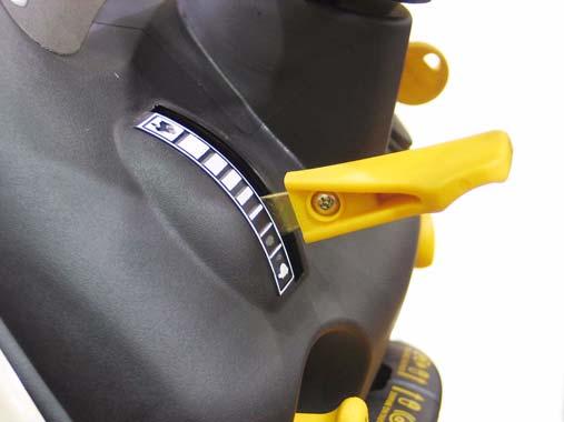
15.7. Remove the knob from the throttle lever using a phillips head screwdriver, then remove the screws that hold the throttle assembly to the dash panel. See Figure 15.7.
Throttle
Lever
Figure 15.7
15.8. On models with a separate choke cable, disconnect the choke cable at the engine end. If the technician prefers, they may also choose to dis connect the throttle cable at the engine end. 15.9. Remove the remaining screws that hold the dash panel to the tractor, and remove the dash. • Two socket-head cap screws (T-40) at each side of the base of the dash panel (four total).


