
4 minute read
28. TRANSAXLE SERVICE AND MAINTENANCE: HYDROSTATIC LT

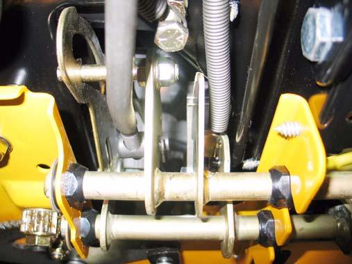
27.3. Remove and discard both cotter pins that secure the brake pedal shaft and the hydro drive pedal shaft to the frame. See Figure 27.3.
Cotter pins
Figure 27.3
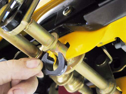
27.4. Remove the large washers and inner bushings from each shaft. 27.5. Press both shafts as far outward as possible, and pry the worn bushings out of the bracket. See Figure 27.5.
Figure 27.5
NOTE: A pair of vice-grips and a plate can be used to press the end of the shaft flush with the edge of the bracket to aid removal of the bush ings. NOTE: The inner bushing is a hex flange bushing. The outer bushing is similar, but has one open side. The “tooth” in the top facet of the bracket that supports the bushing registers in open side of the bushing. 27.6. Clean any corrosion or dirt from the surfaces where the pedal shafts contact the bushings, and slip the new bushings into place. See Figure 27.6.
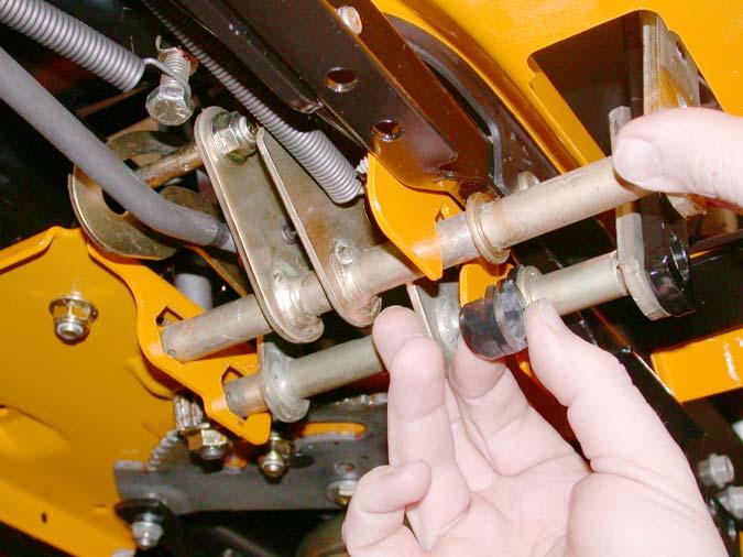
Clean
Figure 27.6
NOTE: Lubrication with grease may accelerate bushing wear. If lubrication is applied it should be in dry form such as graphite or PTFE (Teflon). 27.7. Secure the inner bushings with new cotter pins and the flat washers that were previously removed.
27.8. Move the pedal through it’s range of travel to check for bind. If binding is encountered: • Bind in a portion if the travel may be caused by a bent pedal shaft. • Constant bind is likely to be caused by a bent bracket.
• Also check for interference between the park brake and cruise control interlocks.
27.9. Correct any binding condition. 27.10.Connect the brake rod to the brake pedal shaft, and secure it with a new cotter pin. 27.11. After any brake service is performed, test the brakes as described in Section 23, then testdrive the tractor in a safe area that is free of haz ards, obstacles, and by-standers before returning the tractor to service.
28. TRANSAXLE SERVICE AND MAINTENANCE: HYDROSTATIC LT
28.1. In normal use, the transaxle should last the life of the tractor with minimal maintenance.
28.2. Because the transaxle dissipates heat through air-cooling of the housing, it must be kept clean of dirt and debris, and the cooling fan should be replaced immediately if damaged. 28.3. Cleanliness is vitally important when doing any service work that might expose the fluid or inter nal parts to any form of contamination. Clean thoroughly around any fittings, parts, or seals that are to be removed prior to removal. 28.4. Pressure washing is not recommended, and may contaminate the transmission fluid. Dam age caused by contaminated fluid is not warrantable.
28.5. Before commencing internal repairs, eliminate all possible external performance issues: • Dragging brake • Maladjusted linkage • Partially open relief valve • Slipping traction drive belt/ low engine speed 28.6. The transaxle contains .600 to .632 gal of 20W50 motor oil with an API classification of SH/CD.
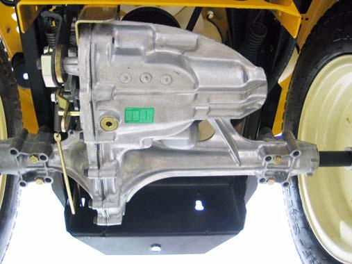
28.7. Fill through the port at the top of the transaxle. Fluid will spill into the plastic over-flow reservoir as the fluid capacity is reached. See Figure 28.7.
Over-flow reservoir
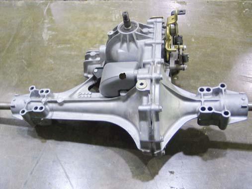
Fill port
Figure 28.7
NOTE: Some transaxles may be painted black, depending on the year of production. NOTE: The plastic over-flow reservoir has a plastic vent cap at the top. This is strictly a vent cap. Attempting to add fluid through the vent cap will fill the over-flow reservoir, but will not add to the level of fluid in the transaxle.
NOTE: This oil (fluid) should not have to be changed in the normal service life of the tran saxle unless it develops a leak or becomes contaminated.
28.8. If the transaxle develops a leak, identify and repair the leak to prevent further damage. 28.9. To drain the oil, Hydro-Gear recommends removal of the transaxle, for draining through the fill port. 28.10.A new addition to the transaxle is a drain plug. Depending on the date of manufacture, this plug may or may not be present. See Figure 28.10.
Drain plug
Figure 28.10
28.11. Any time the fluid has been drained from a hydrostatic transaxle, the air should be purged from the system on initial start-up. 28.12. To purge the air from the hydraulic system in the transaxle:
• Open the relief valve. • Start the engine. • Slowly cycle the drive pedal from full speed forward to full speed reverse 5 or 6 times, taking about 10 seconds to complete a single cycle. • Stop the engine and check the fluid level at the fluid level port near the back of the right side axle housing. The plug can be removed with a 1/4” Allen wrench. Top-up as necessary. • Close the relief valve.
• Start the engine.


