5 minute read
26. BRAKES AND BRAKE ADJUSTMENT: HYDROSTATIC LT


25.8. As the hydro control rod moves back on the input arm, it first moves a ground contact against the reverse safety switch. See Figure 25.8.
Reverse switch
Figure 25.8
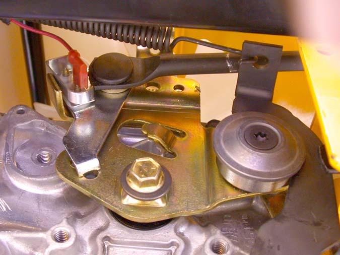
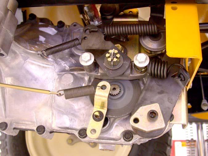
25.9. After the switch contacts the ground, the hydro control rod reaches the end of the lost-motion slot, and begins to push the arm forward, to the reverse position. Excessive lost motion will result in loss of ground speed in reverse. 25.10.As the hydro control rod is pushed rearward, it draws the cam (front) surface of the input arm upward, forcing the neutral return arm forward, applying more tension to the return spring. See Figure 25.10.
Return spring
Figure 25.10
25.11. The point that the neutral return arm draws the input arm to is determined by the position of the roller on the neutral return arm: • If the roller is moved higher, the input arm will move in the direction that causes forward drive. • If the roller is moved lower, the input arm will move in the direction that causes reverse drive.
25.12.The roller is moved up or down by rotating the house-shaped eccentric that the neutral return
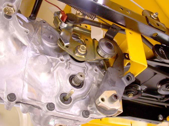
arm pivots on. See Figure 25.12.
Figure 25.12
25.13.Loosen the eccentric using a 1/4” Allen wrench, and rotate it to adjust the roller up or down, as required to center the input arm in neutral. 25.14.Tighten the socket head cap screw to lock the adjustment, and check to confirm that the adjust ment is correct.
25.15.After confirming that the transaxle is correctly adjusted: • Adjust and reconnect the hydro control rod if it has been removed.
• Install the right rear wheel on the tractor if it was removed.
• Test the operation of the drive system in a safe area that is free of hazards, obstacles, and bystanders.
• Install the cutting deck, test all safety features, and return the tractor to service if everything works properly.
26. BRAKES AND BRAKE ADJUSTMENT: HYDROSTATIC LT
26.1. On hydrostatic garden tractors, most of the braking force is generated within the transaxle: when in Neutral, with the brakes released, the tractor will still be very difficult to push unless the relief valve has been opened. The brake functions mainly as a parking brake.
26.2. When properly adjusted, the brake should do two things: it should stop and hold the tractor when applied, and it should not drag when released.
26.3. To check that the brakes hold the tractor:
• Open the relief valve. • Set the parking brake. • Attempt to push the tractor. • The wheels should skid without rotating. • If the brakes do not hold the tractor, the adjustment needs to be tightened or the brakes need to be repaired. 26.4. To check that the brakes do not drag: • Open the relief valve. • Release the parking brake. • Attempt to push the tractor - it should move with about 40 lbs of force. More force indicates drag. • If the brakes drag, they need to be adjusted or repaired. 26.5. There is no linkage adjustment. All adjustment is done at the brake caliper. 26.6. To reach the brake caliper, lift and safely support the right rear corner of the tractor. 26.7. Remove the right rear wheel of the tractor using a 3/4” wrench.
26.8. Hydro-Gear transaxles use a castle nut locked with a cotter pin. See Figure 26.8.
Castle nut
Figure 26.8
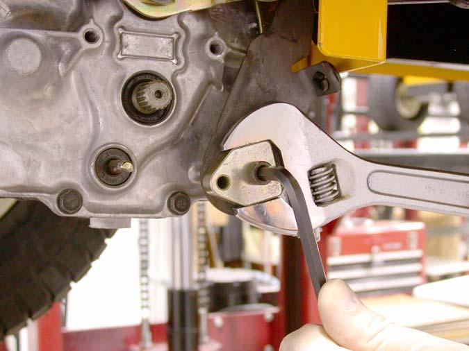
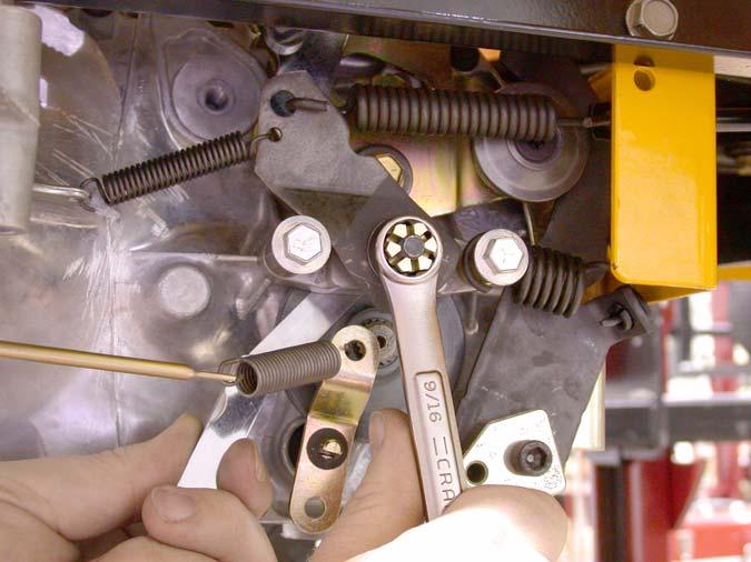
26.9. Insert a .015” feeler gauge between the brake rotor and the outer brake pad. There should be slight drag on the feeler gauge. 26.10.If the feeler gauge is too loose, or will not go in, brake caliper adjustment is necessary. 26.11. Remove and discard the cotter pin. A 9/16” wrench will turn the adjustment nut. See Figure 26.11.
Figure 26.11
26.12.Tighten the nut to reduce the clearance. Loosen the nut to increase the clearance.
26.13.Check the movement of the brake arm:
• The brake arm should move forward as the brake is applied. • The return spring should draw the brake arm back against the spacer when the brakes are released.
26.14.Visually check the thickness of the brake pads: they are visible within the caliper. 26.15.Check the brake rotor:
• Confirm that the brake rotor floats on the splined shaft by sliding it in and out with light finger pressure.
• If it binds on the shaft it may cause brake drag and reduced holding performance. • A rotor that has been dragging will frequently be discolored by the heat (blue).
26.16.If the brakes are dragging or worn, or if the rotor needs to be removed from the shaft disconnect the brake return spring where it attaches to the transmission housing. See Figure 26.16.
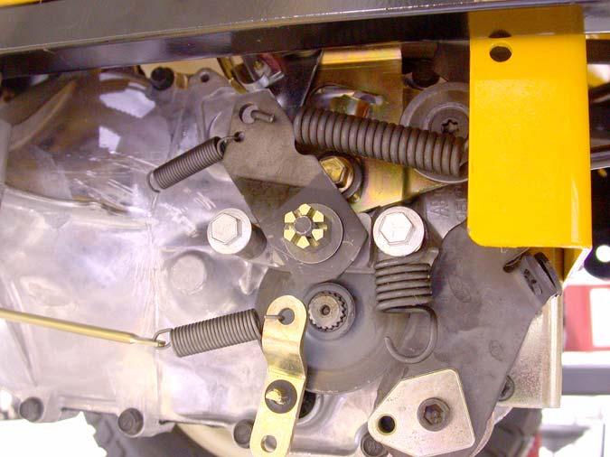
Brake return spring
Figure 26.16
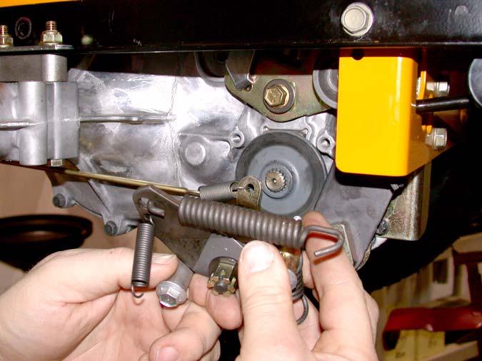
26.17.Using a suitable tool, remove the large hydro return spring where it attaches to the hydro arm. 26.18.Using a 7/16” wrench, remove the two bolts that hold the caliper to the transaxle. See Figure 26.16. 26.19.Once the caliper is removed form the transaxle, the brake arm can be unhooked from the spring that connects it to the brake linkage. See Figure 26.19.
26.20.In order to remove the rotor and gain access to the fixed brake pad you will have to pry the retaining clip securing the hydro relief arm to the
hydro relief valve shaft. See Figure 26.20.
Retaining clip
Figure 26.20
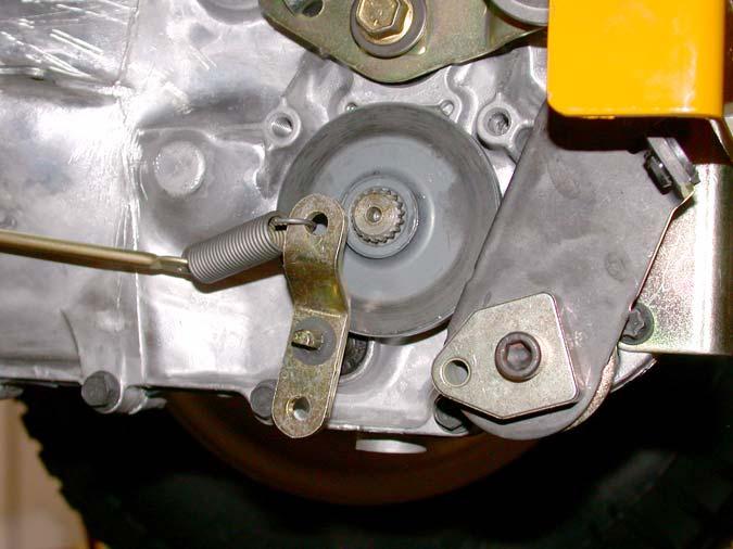
NOTE: During re-assembly you will have to replace the retaining clip with a new one. 26.21.The brake rotor should slide-off of the splined shaft, providing access to the fixed brake pad. See Figure 26.21.
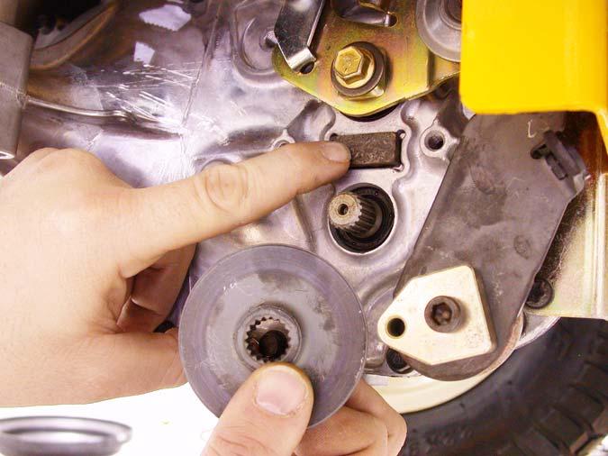
Figure 26.19