5 minute read
34. TRANSAXLE REPLACEMENT: HYDROSTATIC GT


• Install the screw O-rings. • Install the lower cover without sealant, to align the cover and manifold. Secure it with the 11 perimeter screws. • Remove the lower cover, and apply sealant to the mating surfaces where the cover meets the transaxle housing. • Install the lower cover, tightening the screws to a torque of 135 to 185 in-lbs. • Position a new O-ring seal in the charge pump housing, and place the gerotor in the housing. If one edge of the outside of the gerotor is slightly rounded, it goes into the housing first. The flat edge rides against the lower cover. • Position the charge pump, rotating as necessary to align the gerotor pump with its drive shaft and to align the charge pump housing index marks. • Install the two socket head cap screws that secure the charge pump, and tighten them to a torque of 87 to 108 in-lbs. 33.19.Allow the bottom cover sealant to cure according to the sealant manufacturer’s instructions, then fill the transaxle with fluid.
33.20.Any time the transaxle fluid has been refilled, it will be necessary to purge the air from the pumps. Air in the drive system will cause: • Noisy operation • Lack or loss of power • High operating temperatures 33.21. To purge the air from the hydraulic system in the transaxle:
• Open the relief valve. • Start the engine. • Slowly cycle the drive pedal from full speed forward to full speed reverse 5 or 6 times, taking about 10 seconds to complete a single cycle. • Stop the engine and check the fluid level at the fluid level port near the back of the right side axle housing. The plug can be removed with a 1/ 4” Allen wrench. Top-up as necessary. • Close the relief valve.
• Start the engine. • Slowly cycle the drive pedal from full speed forward to full speed reverse 5 or 6 times, taking about 10 seconds to complete a single cycle. • Stop the engine and check the fluid level at the fluid level port near the back of the right side axle housing. The plug can be removed with a 1/ 4” Allen wrench. Top-up as necessary. • Repeat as necessary until the transaxle operates normally. 33.22.Refer to Hydro-Gear manual BLN-52359 for complete repair instructions.
34. TRANSAXLE REPLACEMENT: HYDROSTATIC GT
34.1. Warrantable failures on Cub Cadet tractors are to be repaired by replacing the transaxle. Failed, warrantable transaxles will be called-back through Cub Cadet’s vendor recovery system. Failures of Hydro-Gear transaxles are rare. 34.2. Outside of warranty, Hydro-Gear transaxles may be repaired or replaced at the discretion of the customer and servicing dealer. 34.3. Before condemning a transaxle, eliminate all possible external performance issues: • Dragging brake • Maladjusted linkage • Partially open relief valve • Slipping traction drive belt/ low engine speed 34.4. Remove the cutting deck to gain access to the linkages that will need to be disconnected. 34.5. Lift and safely support the rear of the tractor. 34.6. Remove the rear hub caps, then the rear wheels using a 3/4” wrench. See Figure 34.6.
Figure 34.6
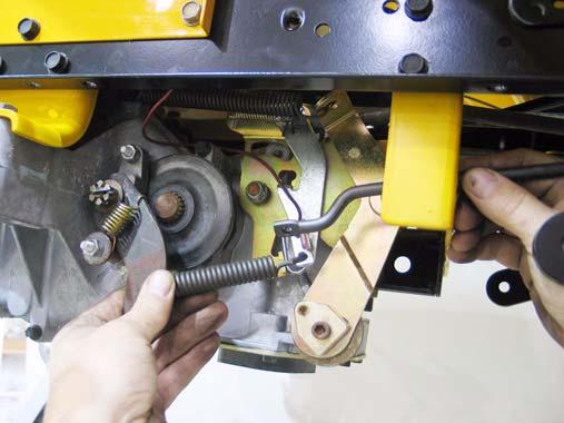
34.7. Disconnect the front of the brake rod from the brake pedal shaft by removing the cotter pin, and pulling the “L” at the forward end of the rod out of the hole in the brake pedal shaft. 34.8. Use the resulting slack in the linkage to disconnect the rear of the brake rod from the spring that joins it to the arm on the caliper. See Figure 34.8.
Figure 34.8
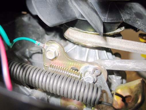
34.9. Remove the brake rod from the tractor. 34.10.Unplug the wire from the reverse safety switch (Red wire w/black trace on Rev-Tek equipped models, Yellow wire w/black trace on others). 34.11. Disconnect the ground wire from the transaxle using a 3/8” wrench and a 7/16” wrench. See Figure 34.11.
Ground wire
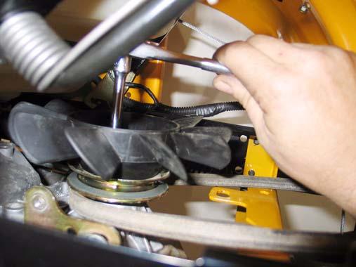
34.12.Disconnect the control rod from the arm on the hydro.: • Remove the hairpin clip that secures the rod to the arm, just in front or the connection point for the ground wire. • Carefully withdraw the rod from the spring and the reverse safety switch lost-motion arm. 34.13.Remove the fan from the input pulley on the
transaxle using 5/16” wrench. See Figure 34.13.
Figure 34.13
34.14.Draw the traction drive belt off of the fixed idler pulley to create slack, then work the belt off of the double idler pulleys, similar to the method described in the “TRACTION DRIVE BELT: HYDROSTATIC GT” section of this manual.
34.15.Slip the belt off of the input pulley. See Figure 34.15.
Figure 34.11
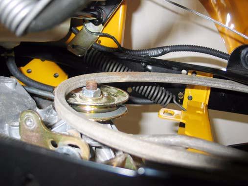
Figure 34.15
34.16.Disconnect the hydro relief rod from the relief valve by removing the hairpin clip. Lift the rod off of the arm that controls the valve, and remove the rod from the tractor. See Figure 34.16. Relief valve
Figure 34.16
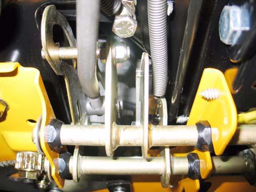
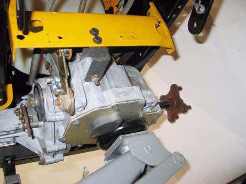
34.17.Detach the transaxle vent tube from the left frame channel of the tractor. 34.18.Support the transaxle with a hydraulic jack. 34.19.Remove the two screws that connect the transaxle to the stabilizer bracket using a 9/16” wrench. See Figure 34.19. Remove these 2 screws 34.20.Remove the pair of nuts and bolts that fasten each axle housing of the transaxle to the brack ets on the tractor frame. Use a pair of 1/2”
wrenches. See Figure 34.20.

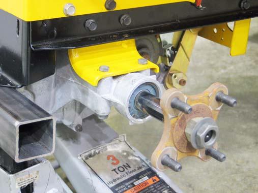
Remove these 2 nuts and
bolts
Figure 34.19 Figure 34.20
34.21.Carefully lower the transaxle to the ground. 34.22.Installation notes are as follows:
34.23.Fill the transaxle with fluid before installing it in the tractor. Some dealers have devised ways to manually drive the input shaft and purge the air from the drive system on the bench, prior to installation.
34.24.If bench purging is not available, follow the purging instructions described in the “TRANSAXLE SERVICE AND MAINTENANCE: HYDRO STATIC GT” section of this manual after the transaxle is installed.
34.25.Reverse the removal process to install the transaxle.
• Tighten the screws to the torque bracket to a torque of: 35 ft.-lbs. • Tighten the bolts holding the axle housings to the brackets to a torque of: 250 in-lbs. • Tighten the screws holding the fan to the pulley to a torque of: 30-35 in-lbs. • Tighten the lug nuts to a torque of: 34.26.Test run the tractor in a safe area that is free of hazards, obstacles, and bystanders to confirm correct operation and adjustment before install ing the cutting deck. Make any necessary adjustments.