
2 minute read
5. REAR FENDER REMOVAL


5. REAR FENDER REMOVAL
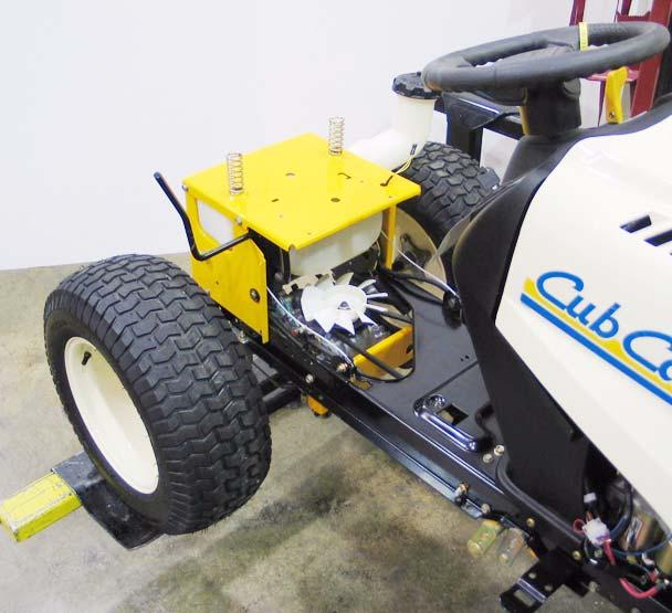
5.1. It is necessary to remove the fender assembly for access to the following service areas: See Figure 5.1.
Figure 5.1
• Fuel tank (hydrostatic drive riders) • Lift-shaft assembly (except bushings) • Deck lift cable removal • Wiring harness inspection or removal • Dash panel removal • Traction drive belt idler pulley removal • Traction drive belt tension arm removal NOTE: At first-glance, fender removal appears to be a substantial job. Skilled mechanics can typically remove the fenders from a 1000 Series Cub Cadet tractor in about 15 minutes, with an equal amount of time required for installation. 5.2. Disconnect the ground cable from the negative battery post using a 7/16” wrench. 5.3. Remove the cutting deck from the tractor. 5.4. Remove the rubber grip from the cutting deck height control handle atop the right rear fender.
See Figure 5.4.
Figure 5.4
5.5. Disconnect the two yellow wires from the seat safety switch mounted to the left side seat bracket. See Figure 5.5.
Safety Switch Connectors

Figure 5.5
5.6. Release the gold colored extension spring from the left side seat bracket using a length of starter rope or a spring removal tool. • gold colored spring: left seat bracket • red spring: right seat bracket • Only the gold colored spring must be removed because it blocks access to the bolts that hold the seat bracket to the frame.
5.7. Remove the four bolts that hold the seat brackets to the frame using a 1/2” wrench. 5.8. Remove the seat to a safe location.
5.9. Remove the hydro control pedal (or speed control pedal on CVT equipped models) using a T40 driver. See Figure 5.9. T-40 Screws
Figure 5.9
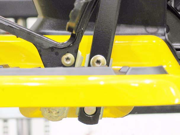
5.10. Remove the brake pedal using a T-40 driver (upper screw) and a 9/16” wrench (lower screw). 5.11. Remove the nuts from the carriage bolts that secure the front edge of each running board to the frame bracket that supports it. See Figure 5.11.
Figure 5.11
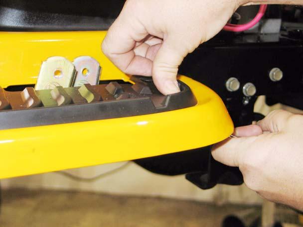
• Apply thumb pressure to the rubber foot pad, directly above the nut / carriage bolt to hold the square boss on the nut into the bracket, to prevent rotation. 5.12. Peel-back the rubber foot pad to reach and
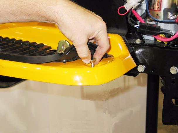
remove the carriage bolt. See Figure 5.12.
Figure 5.12
5.13. Carefully peel-up each rear corner of the larger instruction label located between the foot pads, revealing two screws that hold the fender
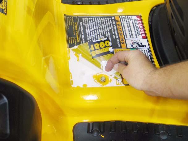
assembly to the frame. See Figure 5.13.
Figure 5.13
NOTE: If the previous steps are done with care, the label can be reapplied, using some spray-on contact adhesive if necessary. • If the label shows signs of becoming damaged by the peeling-back process, it should be replaced during reassembly. • To identify and order a replacement label, note the number printed on the lower right corner of the label (“S32484 AC” typical). That number, with a 777 prefix (777-S32484 AC) is usually the part number of the label.


