7 minute read
31. DRIVE SYSTEM ADJUSTMENT: HYDROSTATIC GT


30.13.The double idler pivot bracket is held to the frame by the same bolt that holds the fore-most of the two pulleys. The rear pulley can be easily removed from the bracket. It is necessary to take the fenders off to remove the front pulley or the bracket itself.
30.14.Install the drive belt by reversing the order of the removal process. • Apply anti-seize compound to the crankshaft before installing the PTO clutch. • Tighten the crankshaft bolt to a torque of 38-50 ft.-lbs. on assembly. • Test the drive system and all tractor safety features in a clear area that is free of hazards and by standers before returning the tractor to service.
31. DRIVE SYSTEM ADJUSTMENT: HYDROSTATIC GT
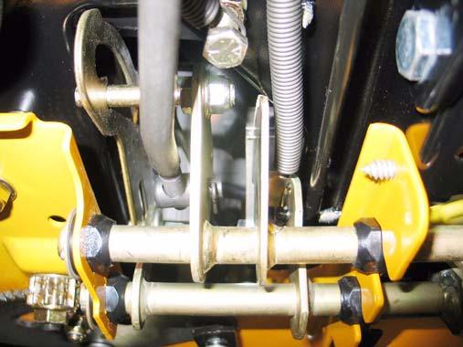
31.1. The relief valve is operated using a heavy rod that is visible at the bottom left corner of the rear of the tractor frame. See Figure 31.1. Relief valve rod
Figure 31.1
31.2. Pulling the rod out and locking it in the upper portion of the keyhole enables the tractor to be pushed, but disables the hydraulics of the drive system by opening a valve that releases the hydraulic pressure from the motor circuit. 31.3. There is no adjustment to the relief valve, but full travel of the linkage should be checked if the drive system is losing power or ground speed. See Figure 31.3.

Relief valve
Figure 31.3
31.4. Symptoms of a linkage that is out of adjustment include:
Low ground speed in either direction with no unusual noises from the transaxle. One possible cause for low ground speed is a linkage that does not transfer all of the pedal travel to the input arm on the transaxle. “Creeping” when the transaxle is in neutral position. Whining or growling when the tractor is in Neutral with the brake applied. • The creeping and whining symptoms usually accompany one-another, indicating that the linkage is not properly centered around Neutral. • Low ground speed in one direction only (Forward or Reverse) may accompany whining, growling or creeping in Neutral if the linkage is out of adjustment. • Low ground speed, accompanied by excessive noise is likely to be an internal problem or a brake that is dragging or out of adjustment. 31.5. Begin linkage adjustment by inspecting the linkage. Linkages on equipment that has been in the field are usually out of adjustment because the linkage is binding, worn, bent, or tampered with. 31.6. Replace any worn or damaged parts before adjusting the linkage.
31.7. Turn-off the engine and allow it to cool before starting to work on the tractor. To gain access to the control linkage, perform the following three steps: 31.8. Remove the cutting deck. 31.9. Lift and safely support the rear of the tractor. 31.10.Remove the rear wheels using a 3/4” wrench. 31.11. Move the control pedal through it’s range of travel (with the parking brake released) and look for the following conditions that will cause loss of linkage motion: • Pedal loose on the pedal shaft. • Loose arm that connects the pedal shaft to the control rod.
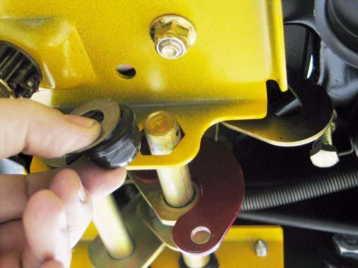
• Worn bushings supporting the pedal shaft. • Worn ferrule or an elongated hole where ferrule connects to pedal shaft. 31.12.Disconnect the control rod from the pedal shaft by removing the cotter pin that secures the adjustable ferrule on the rod to the shaft. See Figure 31.12. Cotter pin
Figure 31.12
31.13.Confirm that the pedal shaft moves freely in the bushings, and does not bind. 31.14.Worn pedal shaft bushings are easily replaced using the following 5 steps. 31.15.Set the parking brake and remove the drive pedal using a T-40 driver. See Figure 31.15. T-40 screws
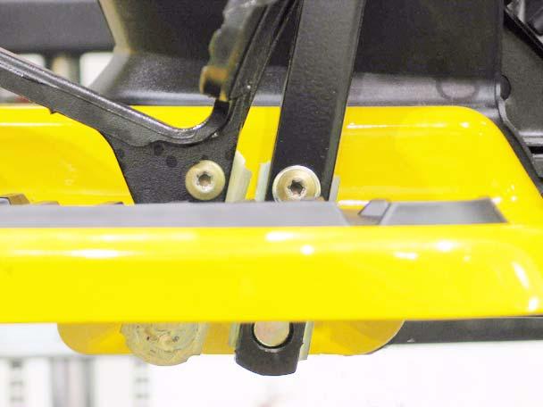
Figure 31.15
31.16.Remove and discard the cotter pin that holds the
inboard bushing in place. See Figure 31.16.
Figure 31.16
31.17.Remove the washer and inboard bushing from the pedal shaft. See Figure 31.17.
Figure 31.17
31.18.Slide the pedal shaft outboard far enough to create clearance to remove the outer pedal shaft bushing, and remove the bushing. See Figure 31.18.
Bushing
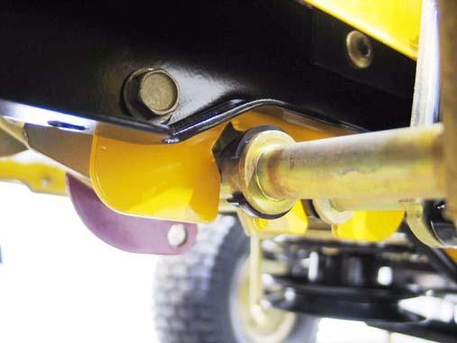
Figure 31.18
NOTE: The inner bushing is a hex flange bushing. The outer bushing is similar, but has one open side. The “tooth” in the top facet of the bracket that supports the bushing registers in open side of the bushing. 31.19.Clean any corrosion or dirt from the surfaces where the pedal shaft contacts the bushing, and slip the new bushings into place. NOTE: Lubrication with grease may accelerate bushing wear. If lubrication is applied it should be in dry form such as graphite or PTFE (Teflon). 31.20.Secure the pedal shaft with a new cotter pin and previously removed washer. 31.21.Install the drive pedal, tightening the screw that secures it to a torque of 250 in-lbs. 31.22.Move the pedal through it’s range of travel to check for bind. If binding is encountered: • Bind in a portion if the travel may be caused by a bent pedal shaft. • Constant bind is likely to be caused by a bent bracket.
• Also check for interference between the park brake and cruise control interlocks.
31.23.Correct any source of binding. The pedal shaft is easily removed at this point. The bracket may be straightened if damage is minor. 31.24.Confirm that no unsafe conditions will arise from starting the engine. 31.25.Start the engine, and operate it at top-no-load speed. Note the operation of the transaxle with the pedal linkage disconnected: An assistant may be required. • Growling or whining with brake applied indicates that the input arm on the transaxle needs adjustment.
• Movement of the left rear wheel or the right drive hub with the brake released indicates that the input arm on the transaxle needs adjustment. • With the hydro control rod disconnected from the pedal shaft, the input arm on the transaxle should return to Neutral.
31.26.If the transaxle does not return properly to neutral, adjust the input arm to correct the issue, then proceed with the following step (23.27). 31.27.If the transaxle returns properly to neutral: • Adjust and reconnect the hydro control rod as described in steps 23.28 through 23.30. • Install the right rear wheel on the tractor, tightening the lug nuts to a torque of. • Lower the tractor to the ground and test the operation of the drive system in a safe area that is free of hazards, obstacles, and by-standers. • Install the cutting deck, test all safety features, and return the tractor to service if everything works properly.
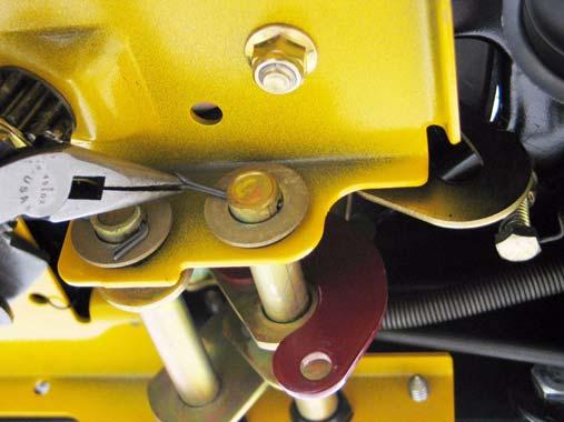
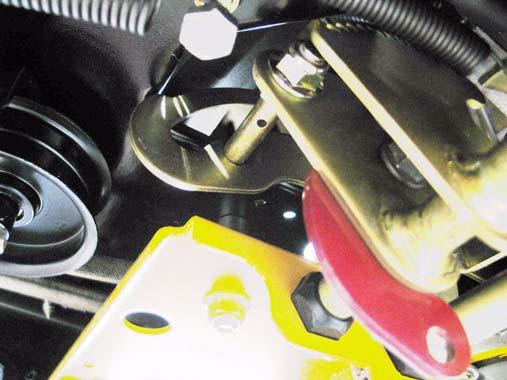
31.28. To adjust the hydro control rod: Find the Neutral position for the control pedal, and set the parking brake. The cam in the parking brake mechanism will lock the pin on the pedal shaft into Neutral. See Figure 31.28.
Pin locked into neutral
Figure 31.28
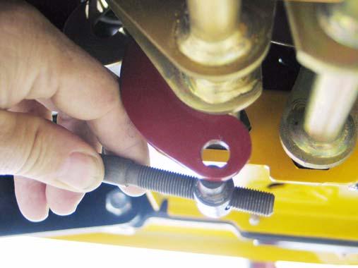
31.29.Thread the ferrule up or down the length of the hydro control rod until the post is centered in the hole that it fits into. At this point, the transaxle and the linkage are both synchronized in Neu tral. See Figure 31.29.
Figure 31.29
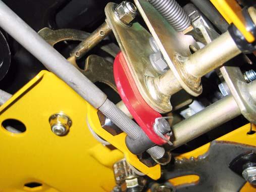
31.30.Secure the ferrule to the arm on the pedal shaft using a new cotter pin. 31.31. To adjust the input arm on the hydro: Confirm that the roller on the return arm draws fully into the valley in the cam surface on the front of the
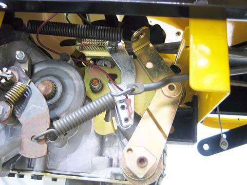
input arm. See Figure 31.31. Roller
Figure 31.31
31.32.As the hydro control rod pulls forward on the input arm, it first moves a ground contact against
the reverse safety switch. See Figure 31.32.
Reverse switch
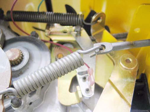
Figure 31.32
31.33.After the switch contacts the ground, the hydro control rod reaches the end of the lost-motion slot, and begins to push the arm forward, to the Reverse position. Excessive lost motion will result in loss of ground speed in reverse.