2 minute read
30. TRACTION DRIVE BELT REPLACEMENT: HYDROSTATIC GT


30. TRACTION DRIVE BELT REPLACEMENT: HYDROSTATIC GT
30.1. Turn-off the engine and allow all parts to cool before beginning work. 30.2. Remove the cutting deck. 30.3. Identify and unplug the wires leading to the electric PTO clutch. See Figure 30.3. PTO clutch wires
Figure 30.3
30.4. Remove the electric PTO clutch from the engine crankshaft using a 5/8” wrench. See Figure 30.4. 5/8” head bolt
Figure 30.4
NOTE: Lower the clutch carefully, keeping track of the hardware on the crankshaft. There are variations between engines, clutches and years: • Spacers above or below the traction drive pulley. • Integral or separate key on traction drive pulley. • Different PTO clutch anti-rotation brackets. 30.5. Slip the belt off of the single fixed idler.

See Figure 30.5.
Figure 30.5
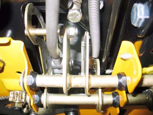
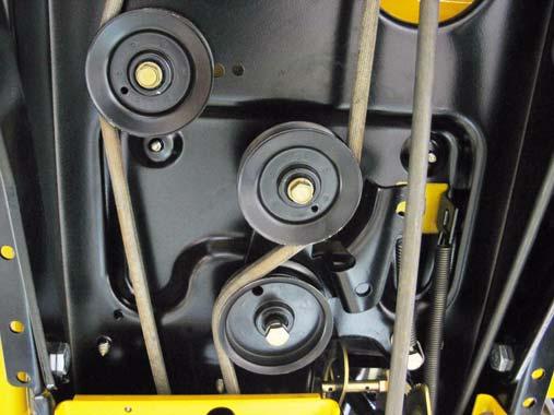
30.6. Carefully release the spring that maintains tension on the double idler bracket using a length of starter rope or an appropriate tool.

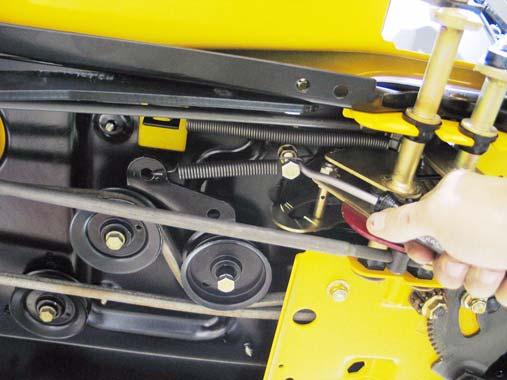
See Figure 30.6.
Figure 30.6
30.7. Slip the drive belt from between the double idler pulleys. NOTE: On some early models, the rear-most pulley (rides against V side of belt) was large enough that the double idler bracket acted as a belt keeper. On those models, it is necessary to loosen the nut and bolt that secure that pulley to the bracket in order to slip the belt past the edge of the bracket.
NOTE: Pulleys may be steel or plastic, depending on when the tractor was built.
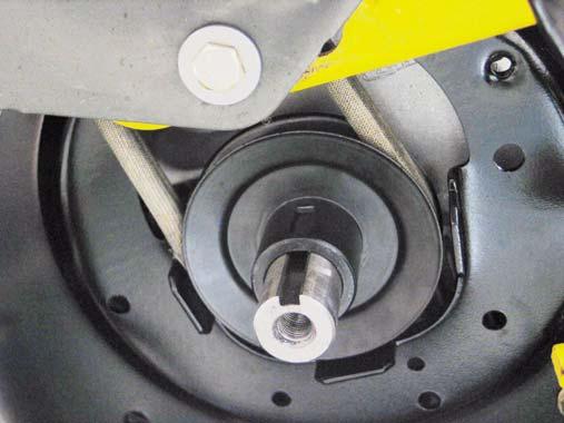
30.8. Slip the crankshaft pulley down far enough to get the belt off of the pulley, and remove the belt from the crankshaft. See Figure 30.8.
Figure 30.8
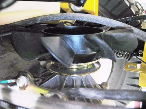
NOTE: Belt keepers that are part of the tractor frame prevent the belt from being removed with out lowering the pulley. NOTE: The pulley may be removed from the crankshaft at the discretion of the technician. • If there is a spacer above the pulley, the end with the radiused inside edge mates with the radiused step on the crankshaft. • If one end of the pulley has a radiused inside edge, that is the end that mates with the radiused step on the crankshaft. 30.9. Carefully work the belt over the top of the cooling fan on the transaxle, and remove it from the trac tor. See Figure 30.9.
30.10.The belt for the G.T. models of the 1500 Series line is Kevlar wrapped. Substituting the polywrapped belt used on the L.T. models is not rec ommended, but the Kevlar belt is an acceptable premium upgrade for the L.T. tractors.
See Figure 30.10. Kevlar belt

Figure 30.10
30.11. If the traction drive belt failed prematurely, identify the cause of it’s demise before installing a replacement. Check the condition of all of the idler pulleys. 30.12.The fixed idler pulley can be removed from later models using a single 1/2” wrench. The bolt that holds the fixed idler to earlier models threads into a 3/8” nut above the tractor frame. The bolt can be removed from the nut using a pair of 9/16” wrenches without removing the fenders. See Figure 30.12.
Fixed Idler