
4 minute read
17. TRACTION DRIVE BELT REPLACEMENT: CVT


16.19.Pivot the subframe down. Be careful of the spacer on the bolt and the hex flange bushing for the steering shaft, they will fall out. 16.20.You now have access to the cruise linkage and cam lock. You also have access the park brake linkage and locking plate. See Figure 16.20. Cruise Control Rod.
Parking Brake Rod
Cam Lock
Figure 16.20
16.21.Remove the hair pin clips on the linkages. Remove the linkages. 16.22.Remove the nut and bolt holding the cruise cam and/or the park brake locking plate. 16.23.Reassemble in reverse order.
CAUTION: Make sure the linkage rods are routed properly before you swing the subframe
17. TRACTION DRIVE BELT REPLACEMENT: CVT
NOTE: There are two drive belts in the CVT system. Because they work together on the variable speed pulley, wear to one belt effects the perfor mance of the other belt. It is strongly recommended that the belts be replaced as a set. 17.1. Remove the cutting deck from the tractor. 17.2. Tilt-up the seat and disconnect the battery cables (ground cable first) using a 7/16” wrench. 17.3. Remove the battery hold-down, remove the battery and the battery tray. See Figure 17.3.

Battery Hold Down
Figure 17.3
17.4. Pull the upper drive belt tensioner pulley rearwards to provide slack in the belt, and roll the belt off of the tensioner pulley. See Figure 17.4.
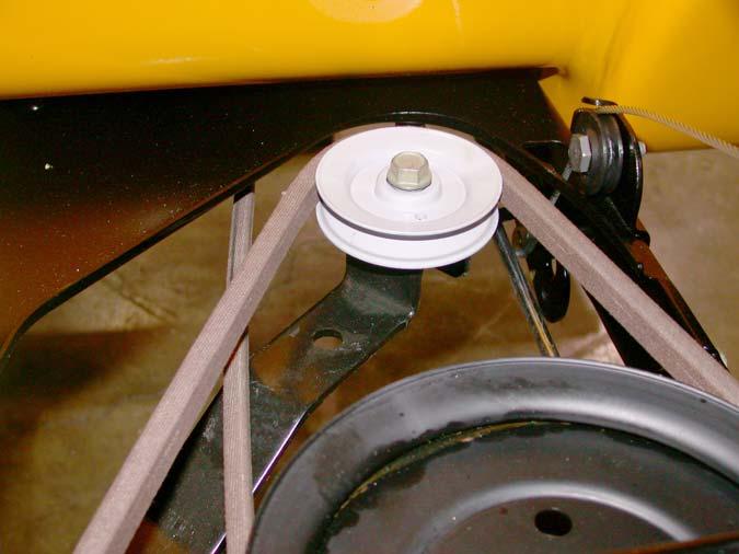
Tensioner pulley
Figure 17.4
17.5. Carefully release the tensioner pulley.
17.6. Using the slack created by taking the belt off the tensioner pulley, slip the belt off of the transaxle input pulley and the upper sheave of the variable speed pulley and remove the belt from the trac tor. You may need to remove the transmission input pulley to get enough clearance to remove the belt. See Figure 17.6.
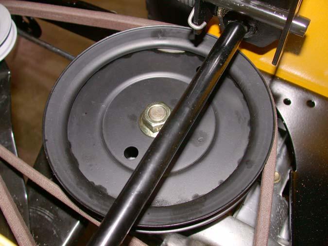
Transmission input pulley
Figure 17.6
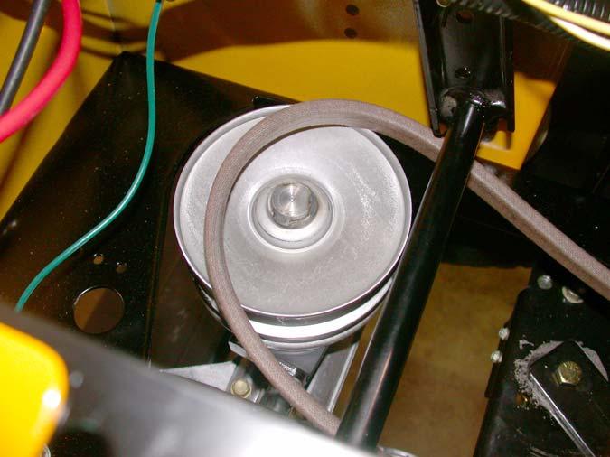
17.7. Loosen but do not remove the bracket that supports the variable speed pulley using a 1/2” wrench. See Figure 17.7. Loosen these bolts
Figure 17.7
NOTE: On 2004 and earlier CVT models, the variable speed pulley was mounted directly to the transaxle housing. On those tractors, remove the variable speed pulley from the trac tor using a pair of 9/16” wrenches. 17.8. Lift the sliding center partition of the variable speed pulley as far as it will go. This should pro vide enough clearance to slip the lower belt off of the variable speed pulley.
Variable speed pulley 17.9. Locate the double idler pulley bracket beneath the tractor. See Figure 17.9.

Double

idler
Figure 17.9
NOTE: This is the pair of pulleys that moves in reaction to drive pedal input from the operator. The further the pedal is depressed, the further the bracket pivots, applying more tension to the belt.
17.10.Slip the lower drive belt off of the pulleys. NOTE: On some 2004 and earlier models, it may be necessary to loosen but not remove the rear-most of the two pulleys (riding against the flat side of the belt) to provide clearance to remove the belt.
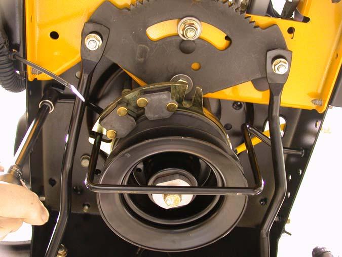
17.11. Disconnect the plug for the PTO clutch wire. It is located on the right side of the tractor, just above the opening in the frame that the wire passes through to reach the PTO clutch. See Figure 17.11.
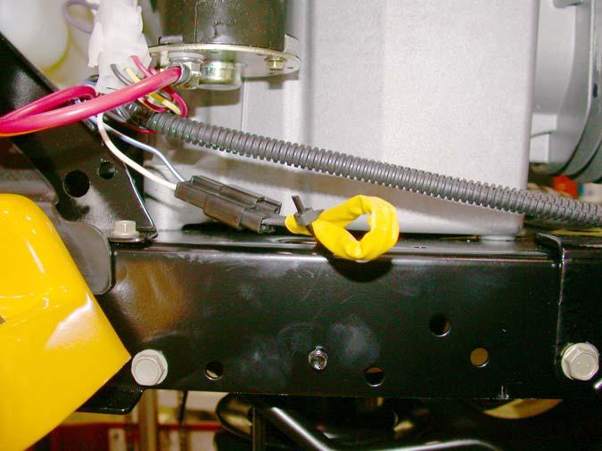
PTO clutch plug
Figure 17.11
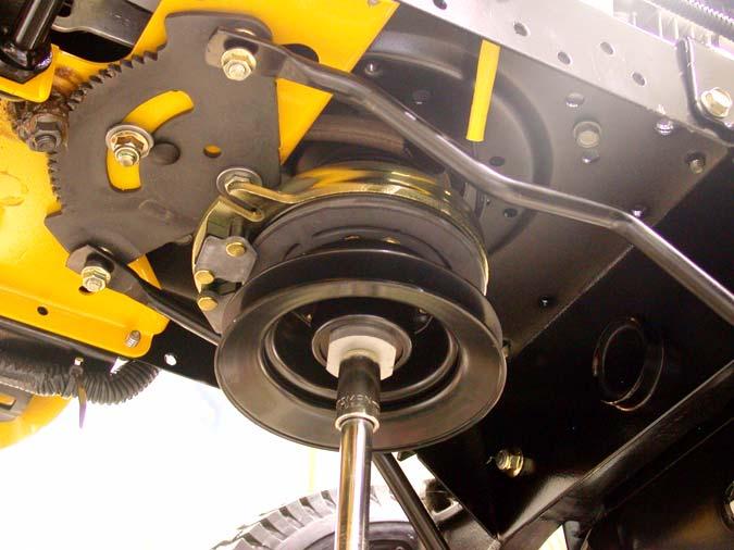
17.12.Remove the bolt that holds the PTO clutch to the crankshaft using a 5/8” wrench. See Figure 17.12.
Figure 17.12
NOTE: If an impact wrench is unavailable it may be necessary to use an improvised piston stop or to hold the flywheel. NOTE: On some models you may have to remove the belt guide on the engine. Remove the 1/2” bolt securing the belt guide to the frame on the left hand side and slide the guide out of the hole on the right hand side. See Figure 17.12.
Bolt
Figure 17.12
17.13.Carefully lower the PTO clutch and any associated hardware off of the crankshaft.
17.14.Lower the drive pulley far enough to allow the belt to slip past the keepers that are stamped into the frame. Slip the belt off of the pulley and
remove the pulley. See Figure 17.14. Stamped belt keepers
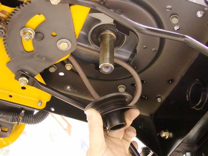
Figure 17.14
NOTE: Keep track of the position of any spacers or washers that accompany the PTO clutch and crankshaft pulley. Several different configura tions have been used.


