6 minute read
32. BRAKES AND BRAKE ADJUSTMENT: HYDROSTATIC GT


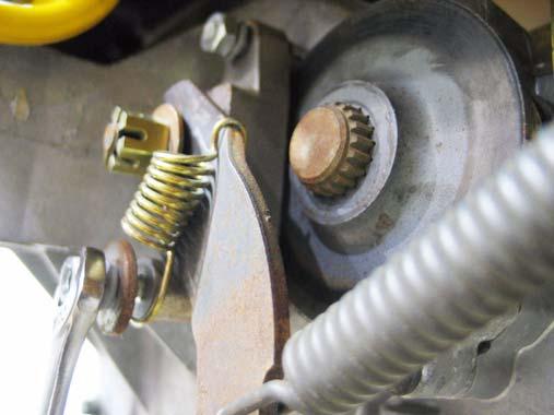
31.34.As the hydro control rod is pushed rearward, it draws the cam (front) surface of the input arm upward, forcing the neutral return arm forward, applying more tension to the return spring. See Figure 31.34.
Spring
Figure 31.34
31.35.The point that the neutral return arm draws the input arm to is determined by the position of the roller on the neutral return arm:
• If the roller is moved higher, the input arm will move in the direction that causes forward drive.
• If the roller is moved lower, the input arm will move in the direction that causes reverse drive.
31.36.The roller is moved up or down by rotating the house-shaped eccentric that the neutral return arm pivots on. See Figure 31.36.
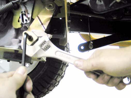
Figure 31.36
31.37.Loosen the eccentric using a 1/4” Allen wrench, and rotate it to adjust the roller up or down, as required to center the input arm in Neutral. 31.38.Tighten the socket head cap screw to lock the adjustment, and check to confirm that the adjust ment is correct by repeating step 23.25. 31.39.After confirming that the transaxle is correctly adjusted: • Adjust and reconnect the hydro control rod as described in steps 23.28 through 23.30. • Install the right rear wheel on the tractor, tightening the lug nuts to a torque of. • Lower the tractor to the ground and test the operation of the drive system in a safe area that is free of hazards, obstacles, and by-standers. • Install the cutting deck, test all safety features, and return the tractor to service if everything works properly.
32. BRAKES AND BRAKE ADJUSTMENT: HYDROSTATIC GT
32.1. On hydrostatic garden tractors, most of the braking force is generated within the transaxle: when in Neutral, with the brakes released, the tractor will still be very difficult to push unless the relief valve has been opened. The brake functions mainly as a parking brake. 32.2. When properly adjusted, the brake should do two things: it should stop and hold the tractor when applied, and it should not drag when released.
32.3. To check that the brakes hold the tractor:
• Open the relief valve. • Set the parking brake. • Attempt to push the tractor. • The wheels should skid without rotating. • If the brakes do not hold the tractor, the adjustment needs to be tightened or the brakes need to be repaired. 32.4. To check that the brakes do not drag: • Open the relief valve. • Release the parking brake. • Attempt to push the tractor - it should move with about 40 lbs of force. More force indicates drag. • If the brakes drag, they need to be adjusted or repaired.
32.5. There is no linkage adjustment. All adjustment is done at the brake caliper. 32.6. To reach the brake caliper, lift and safely support the right rear corner of the tractor. 32.7. Remove the right rear wheel of the tractor using a 3/4” wrench.
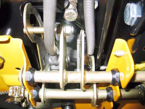
32.8. Hydro-Gear transaxles use a castle nut locked with a cotter pin. See Figure 32.8.

Castle nut
Figure 32.8
32.9. Insert a .015” feeler gauge between the brake rotor and the outer brake pad. There should be slight drag on the feeler gauge. 32.10.If the feeler gauge is too loose, or will not go in, brake caliper adjustment is necessary. 32.11. Remove and discard the cotter pin. A 1/2” wrench will turn the adjustment nut. See Figure 32.11. 32.12.Tighten the nut to reduce the clearance. Loosen the nut to increase the clearance.
32.13.Check the movement of the brake arm:
• The brake arm should move forward as the brake is applied. • The return spring should draw the brake arm back against the spacer when the brakes are released.
32.14.Visually check the thickness of the brake pads: they are visible within the caliper. 32.15.Check the brake rotor:
• Confirm that the brake rotor floats on the splined shaft by sliding it in and out with light finger pressure.
• If it binds on the shaft it may cause brake drag and reduced holding performance. • A rotor that has been dragging will frequently be discolored by the heat (blue). 32.16.If the brakes are dragging or worn, or if the rotor needs to be removed from the shaft, remove the two nuts that hold the caliper to the transaxle using a 7/16” wrench. See Figure 32.16.
Nuts
Figure 32.11
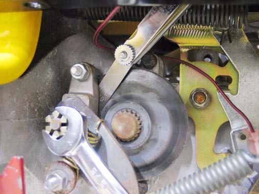
Figure 32.16
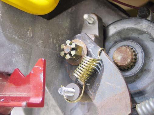
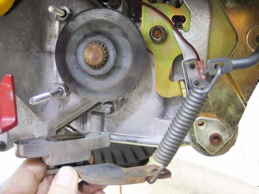
32.17.Remove the return spring. The end with the small hook seats into a notch on the brake arm. The end with the large hook goes around a spacer on the lower stud.
32.18.Once the caliper is removed form the transaxle, the arm can be unhooked from the spring that connects it to the linkage. See Figure 32.18.
Caliper
Figure 32.18
viding access to the fixed brake pad. See Figure 32.19.
Fixed pad
Brake rotor (shoulder faces out) 32.20.A crease in the brake arm acts as a cam. At rest, the ends of the two pins ride in the peak of the
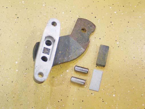
32.19.The rotor should slip-off of the splined shaft, pro
crease: See Figure 32.20.
Figure 32.19 Figure 32.20
• The brake arm pivots on a square-headed stud. • The two pins are forced against the backing plate when force is applied to the arm. • The backing plate rides between the pins and the pad, to prevent the pins form working through the brake pad. 32.21.Replace the pads if they are worn. They frequently last many years unless the brakes have been dragging. 32.22.Be sure the pin bores are clear of dirt and corrosion: either may cause the pins to bind and the brakes to drag. 32.23.On assembly, apply a sparing amount of dry graphite lubricant to the pins and the spots on the brake arm that they contact. Do not allow any lubricant to get on the brake pad.
32.24.Install the brake caliper, tightening the two nuts to 7 to 10 ft.-lbs., then check and adjust the padto-rotor clearance. See Figure 32.24.
Nuts
Figure 32.24
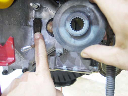
32.25.Lock the adjustment nut with a new cotter pin. 32.26.Install the rear wheel, tightening the lug nuts to a torque of 350 to 500 in.-lbs. Lower the tractor to the ground. 32.27.After any brake service is performed, test the brakes as described in steps 24.2 through 24.4, then test-drive the tractor in a safe area that is free of hazards, obstacles, and by-standers before returning the tractor to service. 32.28.If there is insufficient travel in the linkage to fully apply the brakes, a simple visual inspection should identify the cause. 32.29.Confirm that the brake pedal is firmly attached to the pedal shaft. See Figure 32.29. 32.30.Remove the cutting deck to reach the brake pedal shaft, bushings, and bracket. 32.31.Check for excessive play in the bushings. Replace them if they are worn. 32.32.The inboard brake pedal shaft bushing can be removed by removing the cotter pin and washer
that secure it. See Figure 32.32.
Figure 32.32

32.33.The brake rod must be disconnected to remove the outboard brake pedal shaft bushing. Remove and discard the cotter pin that holds the brake rod to the brake pedal shaft. See Figure 32.33.

Cotter pin
Figure 32.29