
6 minute read
18. DRIVE SYSTEM ADJUSTMENT: CVT


17.15.Remove the belt from the tractor.
NOTE: There were a small number of tractors made using a CVT drive and a 2-speed (L-H-N-R) GT transaxle. The belt must pass over the center mounted gear selector on these mod els for removal. Remove the knob from the gear selector, and remove the shift gait from the fender assembly to provide clearance. 17.16.Assembly notes: • Install the belts by reversing the order of the removal process. • The engine drive pulley is installed on the drive shaft with the key side facing down. • Line up the key on the PTO clutch during assembly. • There is a large flat washer that goes on top of the PTO clutch during assembly. • Torque the PTO clutch bolt during assembly. • When installing the belt guide, make sure that it passes through the cutout in the PTO clutch. this acts as a anti-rotation bracket. See Figure 17.16.
Cutout
Figure 17.16 18. DRIVE SYSTEM ADJUSTMENT: CVT
18.1. Make an operational test of the tractor: • The tractor should not “creep” when the transmission is in gear and the drive pedal is not depressed. • On level ground, with the brake released, the gear selector should slip smoothly into gear. It is normal for gear engagement to be more difficult on a grade, or with the brakes applied because it is more difficult for the drive dogs to engage under load or bind. • The tractor’s forward ground speed should vary smoothly between 0 and 5.2 MPH when the drive pedal is depressed progressively to the end of it’s travel.
• It is normal for the cruise control to hold a mowing speed that is about 10% less than the 5.2 MPH transport speed. • If the tractor performs as described, no adjustment is required.
18.2.
Diagnosis: If the tractor does not move at all, and the engine does not seem to be laboring as the pedal is depressed, the issue may be in the CVT belt system, the shift linkage leading to the transaxle, or within the transaxle itself. 18.3. To isolate the CVT belt system: • Turn-off the engine. • Release the parking brake. • Place the gear selector in any motion gear. • Attempt to push the tractor. • If the tractor rolls, examine the shift linkage. • If the wheels lock when a gear is engaged, the transaxle and shift linkage are not likely to be the problem. 18.4. If the tractor does not move at all, and the engine seems to be laboring as the pedal is depressed, the issue may be in the brake, or within the transaxle itself:
• Turn-off the engine. • Release the parking brake. • Place the gear selector in Neutral. • Attempt to push the tractor. • If the tractor rolls with difficulty, examine the brakes as described in the “BRAKE ADJUSTMENT: CVT” section of this manual.
18.5. If the problem can be isolated to CVT belt drive system, make a visual inspection of the CVT belt drive system: • Turn the engine off, and allow it to cool before starting to work on the tractor. • Remove the cutting deck. • Lift the seat.
• Disconnect the battery cables, negative cable first, using a 7/16” wrench • Remove the battery hold-down.
• Remove the battery and battery tray from the tractor.
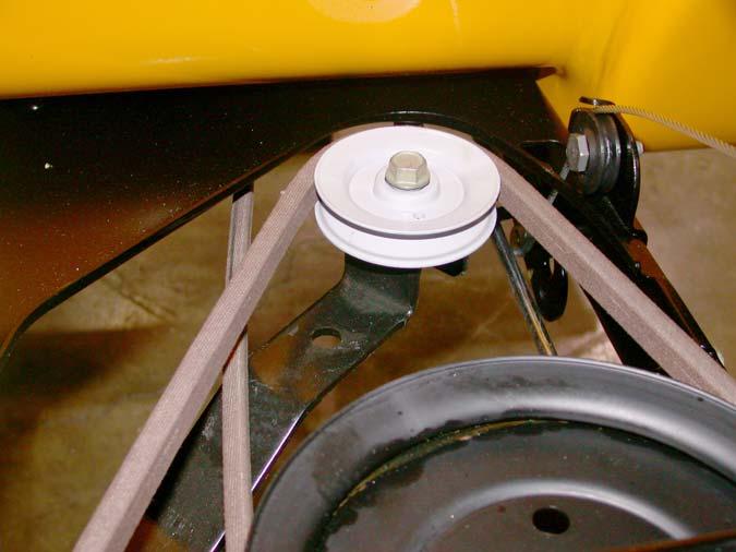
18.6. Inspect the upper drive belt: See Figure 18.6.
Figure 18.6
• Is the upper drive belt correctly positioned on the tensioner pulley, transaxle input shaft pulley, and the upper sheave of the variable speed pulley? • Inspect the type and condition of the belt. • Check the bearing on the tensioner pulley. • Check the tensioner pulley arm: it should return readily to static position under spring tension. • The center partition of the variable speed pulley should move up with light force and down under it’s own weight. 18.7. The pulley on the transaxle input shaft should be firmly attached. • Early production tractors used a splined joint between the pulley and the input shaft. • Current production tractors carry the pulley on a separate hub that fits over the splined shaft. NOTE: The nut securing the pulley should be tightened to a torque of 10-15 ft.-lbs using an 11/ 16” wrench. Over-torquing the nut may shear the input shaft. Replace the belleville washer between the nut and the pulley if it is flattened. NOTE: Some models used a special “fully finished” nut with an extended washer face. Do not replace this nut with a standard nut unless a washer is added between the nut and the pulley. The washer must have a big enough O.D. to fit over the star shape on the pulley adaptor, and must be sufficiently thick to transfer compression
loads (from torquing the nut) directly to the pul ley, not the adaptor. 18.8. Repair any problems found. If the upper drive belt is correct and in serviceable condition, rein stall it. If the upper drive belt needs to be replaced, the lower drive belt should be replaced as well. Refer to the “TRACTION DRIVE BELT REPLACEMENT” section of this manual.
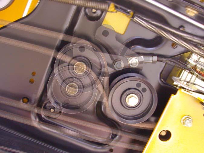
18.9. Operate the drive pedal while observing the movement of the components controlled by the
drive pedal. See Figure 18.9. Observe movement

Figure 18.9
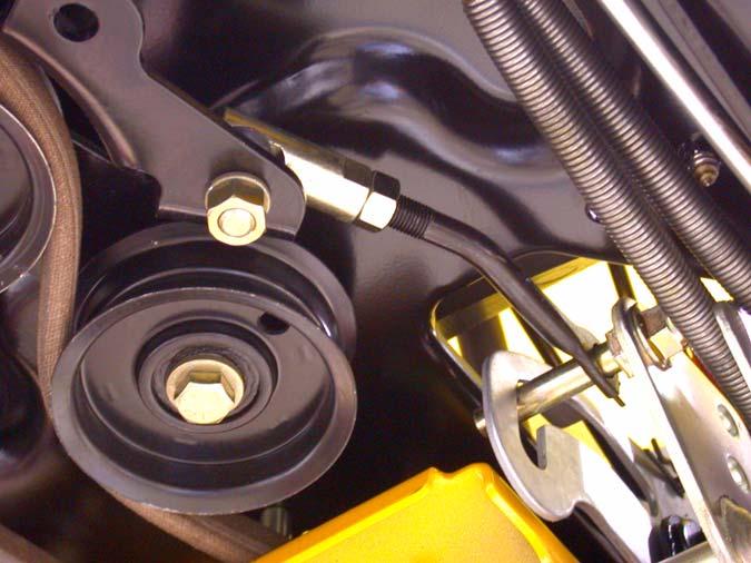
18.10.The double idler bracket should move with about 10 lbs pressure applied to the pedal, and return under spring pressure as the pedal is released. See Figure 18.10.

Figure 18.10
18.11. The empty hole in the double idler bracket should swing through an arc of 1 3/8” when 10 lbs. of force is applied to the drive pedal. See Figure 18.11.
1 3/8” movement
Figure 18.11
18.12.If the measurement is not 1 3/8”, check the type and condition of the lower drive belt. If the lower drive belt is worn or incorrect, replace both drive belts before adjusting the speed control. Refer to the “TRACTION DRIVE BELT REPLACEMENT: CVT” section of this manual. 18.13.If the belts are serviceable and correct, adjust the length of the speed control rod to achieve the correct double idler bracket travel as described in the following steps: 18.14.Loosen the jam nut that locks the speed control rod into the rod-end joint at the double idler bracket with a pair of 9/16” wrenches. See Figure 18.14. Jam nut 18.15.The forward end of the speed control rod connects to a pin attached to the speed control assembly. NOTE: On 2005 production units you can remove the nut on the ball joint and lift it out of the idler bracket on an angle, then skip to step
15.16. See Figure 18.15. 2005 production
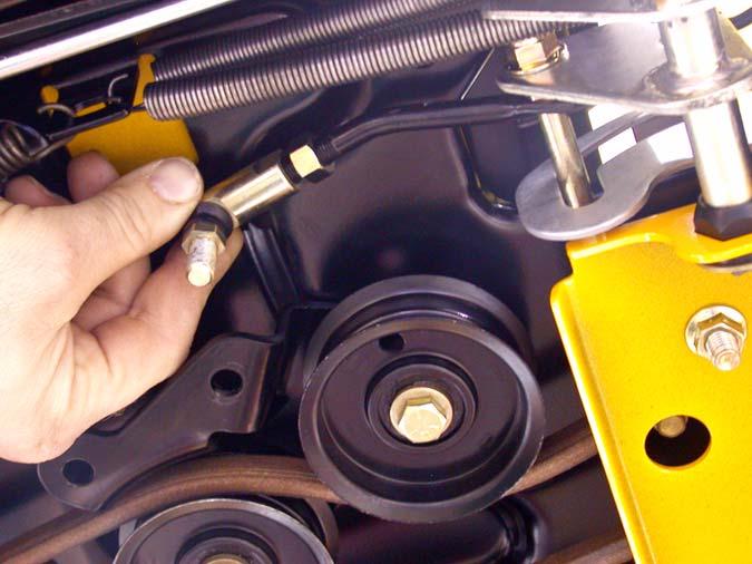
Figure 18.15
• Early production models may have a hairpin clip and washer adjacent to the cam plate that prevents the speed control linkage from moving when the parking brake is applied. • Remove the hairpin clip and washer if so equipped. • Disconnect the pin from the speed control assembly using a pair of 9/16” wrenches. 18.16.Thread the rod in or out of the rod-end as required to achieve the correct linkage travel. 18.17.When adjustment is complete: • Secure the linkage and tighten any loosened fasteners.
• Install the battery tray and battery. • Test the operation of the drive system in a safe area that is free of obstacles, hazards, and bystanders.
• After successful testing, install the cutting deck, test all safety features, and return the mower to service.


