
2 minute read
10. CUTTING DECK REMOVAL


9.9. Remove the four screws going through the muffler support brackets into the muffler mounting bracket. See Figure 9.9. Muffler Support Bracket
Figure 9.9
9.10. The muffler will now slide off of the exhaust pipe(s). 9.11. Remove the screws in the muffler mounting brackets and lift the brackets off of the muffler. 9.12. Reassemble in reverse order.
• 1500 with one piece hood:
9.13. Open hood. 9.14. Remove bumper bilizer bracket. 9.16. Remove the four screws holding the muffler guard to the front muffler support brackets. See
9.15. Remove the two clevis pins in the deck front sta
Figure 9.16. Remove these hex screws. (two on each side)
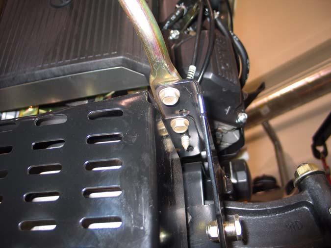
Figure 9.16
NOTE: The rear two screws will be accessible from the top. the front two screws will be acces sible from the bottom.
9.17. Slide the muffler and muffler guard off of the exhaust pipe(s). 9.18. Remove the four screws in the top of the muffler guard. Lift the muffler guard off of the muffler. 9.19. Reassemble in reverse order.
10. CUTTING DECK REMOVAL
10.1. Place the PTO switch in the off position. 10.2. Lower the lift lever to the lowest setting.
10.3. Remove the PTO belt from electric PTO clutch. See Figure 10.3. Electric PTO (earlier production)
Figure 10.3
NOTE: On some models you will need to remove the belt guide first. NOTE: On earlier production models you need to slip the belt off of the idler pulley before you remove the belt from the PTO clutch. 10.4. Pull the rear deck support pins outward from the deck lift arms. See Figure 10.4. Lift arm Deck support pin
Figure 10.4
10.5. Pivot the deck support pins to the rear. 10.6. Raise the lift lever to the highest setting. This will raise the lift arms up and out of the way of the deck assembly. 10.7. Slide the deck forward and release the front stabilizer rod. DO NOT DROP the deck to the
Idler
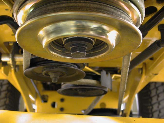
clutch
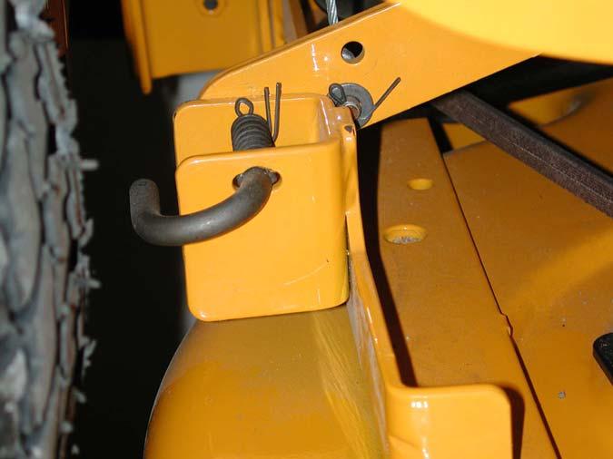
ground. See Figure 10.7.
Front stabilizer rod

Figure 10.7
10.8. Slide the deck toward the right side of he tractor and remove it from under the tractor.
CAUTION: Remove the deck stabilizer assembly from the tractor prior to moving the unit.
NOTE: Depending on the model and deck, some units have a J-bolt for the front stabilizer bar instead of the U-bolt. On those units you can line up the coined spot stamped in the middle of the bolt with the slot in the bracket and slide it off. See Figure 10.8.
U-Bolt Stabilizer
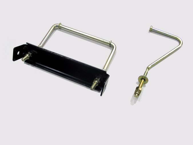
J-Bolt Stabilizer


