
2 minute read
19. BRAKE ADJUSTMENT: CVT


19. BRAKE ADJUSTMENT: CVT
19.1. On CVT-driven lawn and garden tractors, most of the braking force is generated within the tran saxle: when the drive pedal is released, the drive ratio changes, slowing the tractor. The brake brings the tractor to a complete stop, and func tions as a parking brake. 19.2. When properly adjusted, the brake should do two things: it should stop and hold the tractor when applied, and it should not drag when released.
19.3. To check that the brakes hold the tractor:
• Place the gear selector in Neutral. • Set the parking brake. • Attempt to push the tractor. • The wheels should skid without rotating. • If the brakes do not hold the tractor, the brake needs to be adjusted or repaired. 19.4. To check that the brakes do not drag: • Place the gear selector in Neutral. • Release the parking brake. • Attempt to push the tractor - it should move with less than 20 lbs. of force. More force indicates drag. • If the brakes drag, they need to be adjusted or repaired. 19.5. There is no linkage adjustment. All adjustment is done at the brake caliper. 19.6. To reach the brake caliper, lift and safely support the right rear corner of the tractor. 19.7. Remove the right rear wheel of the tractor using a 3/4” socket. 19.8. CVT-driven transaxles use a self locking nut on the brake adjustment. See Figure 19.8.
Lock nut
Figure 19.8
19.9. Insert a .013” feeler gauge between the brake rotor and the outer brake pad. There should be slight drag on the feeler gauge. 19.10.If the feeler gauge is too loose, or will not go in, brake caliper adjustment is necessary. 19.11. A 1/2” wrench will turn the adjustment nut. See Figure 19.11.
Figure 19.11
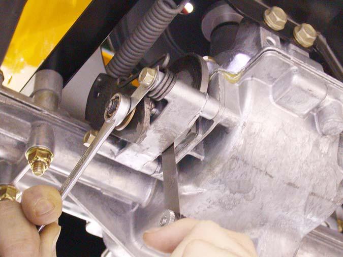
19.12.Tighten the nut to reduce the clearance. Loosen the nut to increase the clearance.
19.13.Check the movement of the brake arm:
• The brake arm should move forward as the brake is applied. • The return spring should draw the brake arm back against the spacer when the brakes are released.
19.14.Visually check the thickness of the brake pads: they are visible within the caliper. 19.15.Check the brake rotor:
• Confirm that the brake rotor floats on the splined shaft by sliding it in and out with light finger pressure.
• If it binds on the shaft it may cause brake drag and reduced holding performance. • A rotor that has been dragging will frequently be discolored by the heat (blue). 19.16.If the brakes are dragging or worn, or if the rotor needs to be removed from the shaft, remove the two bolts that hold the caliper to the transaxle using a 3/8” wrench. See Figure 19.16. 2 Bolts 19.17.Remove the caliper from the transaxle. The brake actuator arm can now be unhooked from the spring that connects it to the linkage. See Figure 19.17.

Caliper
Figure 19.17
19.18.The rotor should slip-off of the splined shaft, providing access to the fixed brake pad.
See Figure 19.18.

Figure 19.16
Fixed brake pad


