
3 minute read
14. LEVELING THE CUTTING DECK


13.5. Remove the notched plate that the deck height control lever seats against in the fender, using a 1/2” socket. See Figure 13.5.
Figure 13.5
13.6. Push the deck height control lever as far forward as it will go, and secure the lever in that position. 13.7. Remove the pulley that carries the deck lift cable using a 1/2” wrench and a 5/8” wrench. 13.8. Remove the E-clip from the same end of the lift shaft that the cable is being removed from. This will allow the lift shaft to be pushed-in slightly, providing clearance for the pin. 13.9. Remove the hairpin clip that secures the pin on the top end of the cable to the arm on the deck lift shaft. See Figure 13.9.

Deck Lift Cable
Figure 13.9
NOTE: Early models used a removable clevis pin. Current production cables have captive pins. 13.10.Remove the hairpin clip that secures the pin to the lift arm, and remove the cable. 13.11. Installation notes:
• Reverse the removal process to install the cables and pulleys. • Because of the dusty environment that many mowers operate in, grease applied to the cable or pulley may accelerate wear rather than prevent it. If any lubricant is used on the pulley, it should be a dry graphite or PTFE based lube. • Replace the pulleys and cables if they show signs of wear. • Check deck level before returning the tractor to service.
• Tighten fasteners to the following torques: Lug nuts 75ft-lbs (Nm) Screws, handle to fender 60 in-lbs (Nm) Screws, plate to fender 144in-lbs (Nm) Shoulder bolts, pulley 144 in-lbs (Nm)
14. LEVELING THE CUTTING DECK
NOTE: Prior to leveling the mowing deck, perform the following steps: • Check the tire pressure. The front tires will be approximately 14 PSI, and the rear tires will be approximately 10 PSI. • Place the tractor on a level surface.
• Depress and lock the parking brake. • Place the cutting deck in cutting position 3 or 4.
SIDE TO SIDE ADJUSTMENT
IMPORTANT:
The cutting deck must be even
side to side.
14.1. Using a work glove or rag, rotate the blades until they are cutting edge tip to cutting edge tip (per pendicular) to the tractor. See Figure 14.1.
Figure 14.1
14.2. Measure the outer blade tips to ground. Both measurements taken should be equal. NOTE: If an adjustment is needed, perform the following steps: 14.3. Loosen (DO NOT REMOVE) the hex cap screw on the left deck hanger bracket using a 1/2” and a 3/4” wrench. See Figure 14.3.
Adjustment Gear Hex Cap Screw
Figure 14.3
14.4. Rotate the 3/4” deck adjustment gear right or left until the deck is level side to side and both blade tips to ground are equal in measurement. 14.5. Retighten the hex cap screw on the left deck hanger using a 1/2” and a 3/4” wrench when the proper adjustment has been achieved.
FRONT TO REAR ADJUSTMENT
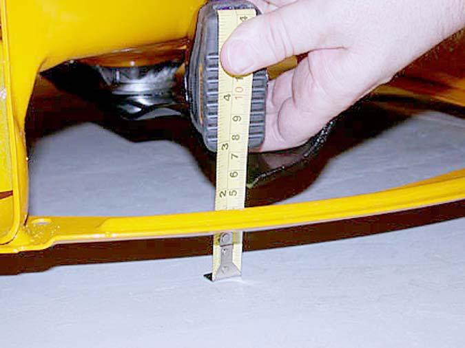
IMPORTANT: The front of the deck will be between 1/4” and 3/8” lower in the front than the rear of the deck.
14.6. Using a work glove or a rag, rotate the blades until they are parallel with the tractor frame. See
Figure 14.6. Blades parallel with frame
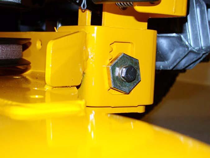
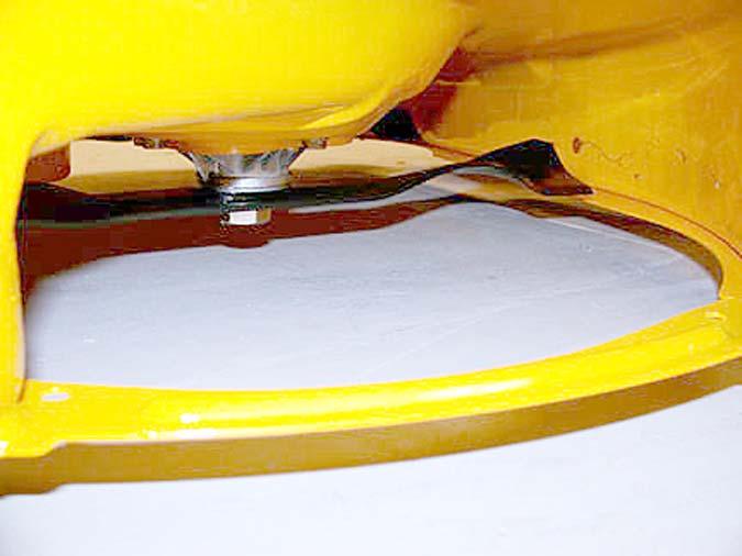
Figure 14.6
14.7. Measure the front blade tips to the ground. 14.8. Measure the rear blade tips to the ground. 14.9. Make certain the front blade tips are 1/4” to 3/8” lower than the rear blade tips. NOTE: If an adjustment is needed, perform the following steps: 14.10.There two types of stabilizer rods. A U-bolt type
and a J-bolt type. See Figure 14.10. U-Bolt Stabilizer
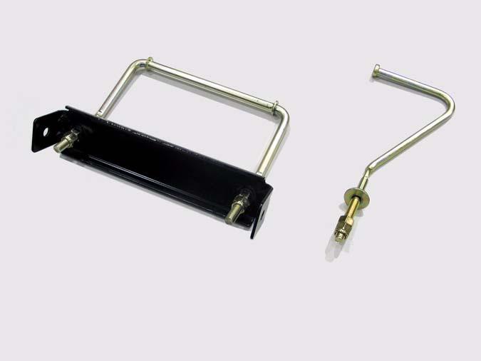
J-Bolt Stabilizer


