
2 minute read
21. TRANSAXLE REPLACEMENT: CVT


NOTE: Lubrication with grease may accelerate bushing wear. If lubrication is applied it should be in dry form such as graphite or PTFE (Teflon). 20.8. Secure the inner bushing with a new cotter pin and the flat washer that was previously removed.
20.9. Move the pedal through it’s range of travel to check for binding. If binding is encountered: • Bind in just a portion of the travel may be caused by a bent pedal shaft. • Constant bind is likely to be caused by a bent bracket.
• Also check for interference between the parking brake and cruise control interlocks.
20.10.Correct any binding condition. 20.11. Connect the brake rod to the brake pedal shaft, and secure it with a new cotter pin. 20.12. After any brake service is performed, test the brakes as described in steps 14.2 through 14.4, then test-drive the tractor in a safe area that is free of hazards, obstacles, and by-standers before returning the tractor to service.
21. TRANSAXLE REPLACEMENT: CVT
• The single speed transaxles used in our CVT riders has evolved over the years. Internals have changed. Some have had the Variable Speed Pulley integrated into the transaxle. If you are replacing a transaxle it is very important to carefully match the transmission part numbers between the old and new. A part number on the transmission case might be the number of the case half. Visually compare the IPL drawing with the actual transaxle to assure a match.
• Before condemning a transaxle, check to make sure the brake is not locking up the transaxle. • Check the drive belts for damage or wear and make sure they are the correct belts and are not the cause of drive problems. • When replacing a transaxle within the warranty period, we have a like-kind exchange program. • Out of warranty transaxles can be serviced. 21.1. Disconnect the battery cables (negative first and then positive). 21.2. Remove the battery hold down, battery and battery tray from the unit. See Figure 21.2.
Battery hold down
Figure 21.2
21.3. Take tension off of the transmission belt idler and remove the belt from around the idler pulley. See Figure 21.3.
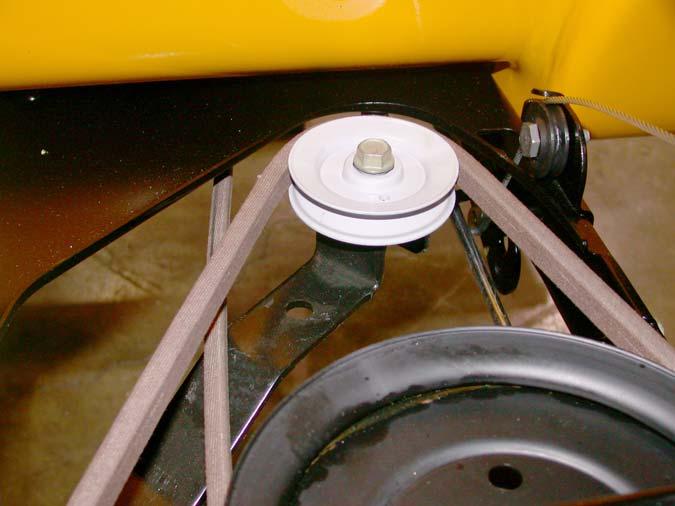
Idler pulley
Figure 21.3
21.4. Using a 7/8 socket and extension, remover the nut securing the transmission pulley to the trans mission. See Figure 21.4.
Transmission pulley
Figure 21.4
21.5. Remove the pulley from the unit. 21.6. Support the frame of the unit to allow removal of both rear wheels. See Figure 21.6.
Figure 21.6
NOTE: Leave room under the rider to allow lowering the transaxle from the unit.
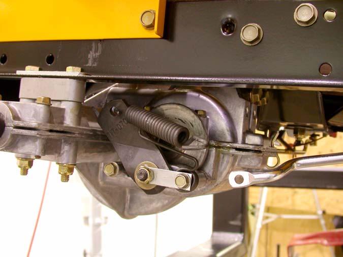
21.7. Disconnect the brake linkage where it connects
to the brake spring. See Figure 21.7. Brake linkageBrake linkage
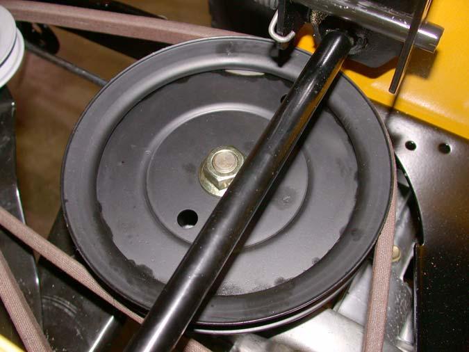
Figure 21.7
21.8. Use white-out to mark the position of the ferrule on the transmission shift rod.
21.9. Remove the hairpin clip securing the transmission shift rod to the transmission. See Figure
21.9. Hairpin clip
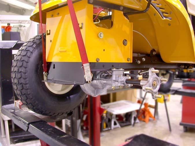
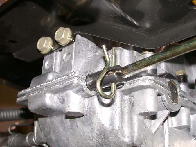
Figure 21.9
21.10.Using a 1/2” socket, remove the two hex screws securing the front of the transmission housing to the transmission support bracket. See Figure 21.9.
21.11. Support the transmission from below.


