
4 minute read
29. TRANSAXLE REPLACEMENT: HYDROSTATIC LT


• Repeat as necessary until the transaxle operates normally. 28.13.Any service beyond fluid change requires removal substantial disassembly of the tran saxle. Refer to Hydro-Gear manual BLN-52261 for complete repair instructions.
29. TRANSAXLE REPLACEMENT: HYDROSTATIC LT
29.1. Warrantable failures on Cub Cadet tractors are to be repaired by replacing the transaxle. Failed, warrantable transaxles will be called-back through Cub Cadet’s vendor recovery system. Failures of Hydro-Gear transaxles are rare. 29.2. Outside of warranty, Hydro-Gear transaxles may be repaired or replaced at the discretion of the customer and servicing dealer. 29.3. Before condemning a transaxle, eliminate all possible external performance issues: • Dragging brake • Maladjusted linkage • Partially open relief valve • Slipping traction drive belt/ low engine speed 29.4. Remove the cutting deck to gain access to the linkages that will need to be disconnected. 29.5. Lift and safely support the rear of the tractor. 29.6. Remove the rear hub caps, then the rear wheels using a 3/4” wrench. 29.7. Remove the rear hub caps, then the rear wheels using a 3/4” wrench. See Figure 29.7. 29.8. Disconnect the front of the brake rod from the brake pedal shaft by removing the cotter pin, and pulling the “L” at the forward end of the rod out of the hole in the brake pedal shaft. See Figure 29.8.
Brake rod
Figure 29.8
29.9. Disconnect the ferrule at the forward end of the speed control rod from the speed control pedal shaft in similar fashion.
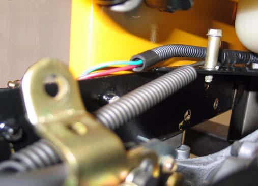
29.10.Unplug the wire from the reverse safety switch (Red wire w/black trace on Rev-Tek equipped models, Yellow wire w/black trace on others). 29.11. Disconnect the ground wire from the transaxle using a 3/8” wrench. 29.12.Remove the fan from the input pulley on the transaxle using 5/16” wrench. See Figure 29.12.
Figure 29.7

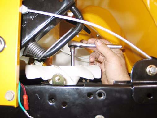
Figure 29.12
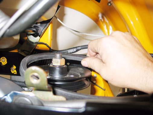
29.13.Draw the traction drive belt off of the fixed idler pulley to create slack, then work the belt off of the double idler pulleys, similar to the method described in the “TRACTION DRIVE BELT: HYDROSTATIC LT” section of this manual.
29.14.Slip the belt off of the input pulley. See Figure 34.15.
Figure 29.14
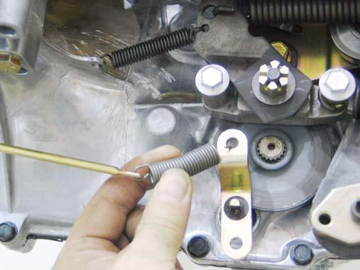
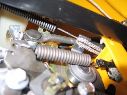
29.15.Disconnect the hydro relief rod from the relief valve by unhooking the extension spring that joins the rod to the arm that operates the valve. See Figure 29.15.
Figure 29.15
29.16.Maneuver the rod to a position where it will not interfere with nor be damaged by the removal of the transaxle. 29.17.Disconnect the deck lift assist spring that hooks to the left side of the transaxle torque bracket using a length of starter rope or a spring removal tool. See Figure 29.17.
A piece of rope
Figure 29.17
29.18.Disconnect the heavy return spring that pulls the control arm toward the rear of the tractor.
See Figure 29.18.
Figure 29.18
Spring
29.19.A length of starter rope is best used to disconnect the front of the spring from the control arm. pass the rope over the torque bracket, and draw downward on the rope to avoid destabilizing the tractor. See Figure 29.19.
Figure 29.19
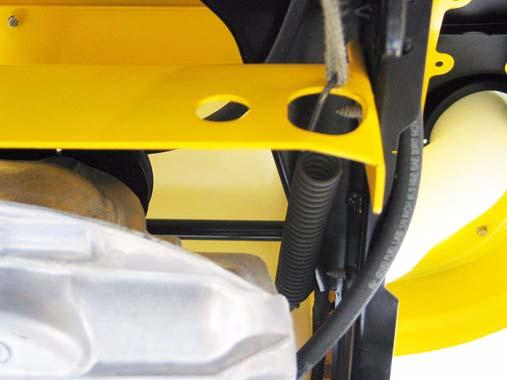
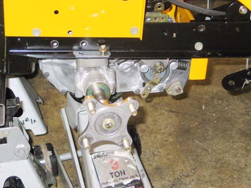
29.20.Support the transaxle with a hydraulic jack. 29.21.Remove the two screws that connect the stabilizer bracket to the frame using a 1/2” wrench. See Figure 29.21. Stabilizer bracket screw
Figure 29.21
29.22.Remove the pair of nuts and bolts that fasten each axle housing of the transaxle to the tractor frame. Use a pair of 1/2” wrenches. NOTE: The bolts pass through a steel reinforcement (sister) plate above the lip on the tractor frame, and an aluminum spacer that fits between the frame and the axle housing.
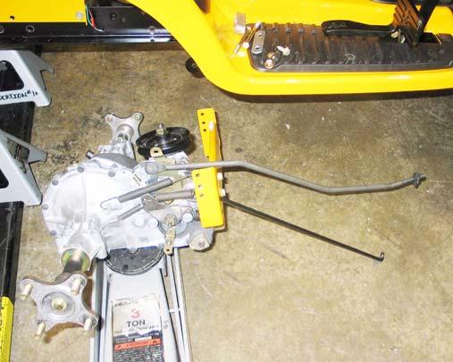
29.23.Carefully lower the transaxle to the ground, complete with torque bracket, brake rod, and hydro
control rod. See Figure 29.23.
Figure 29.23
29.24.Installation notes are as follows:
29.25.Fill the transaxle with fluid before installing it in the tractor. Some dealers have devised ways to manually drive the input shaft and purge the air from the drive system on the bench, prior to installation.
29.26.If bench purging is not available, follow the purging instructions described in the “TRANSAXLE SERVICE AND MAINTENANCE: HYDRO STATIC GT” section of this manual after the transaxle is installed.
29.27.Reverse the removal process to install the transaxle.
• Tighten the screws to the torque bracket to a torque of: 35 ft.-lbs. • Tighten the bolts holding the axle housings to the frame to a torque of: 250 in-lbs. • Tighten the screws holding the fan to the pulley to a torque of: 30-35 in-lbs. • Tighten the lug nuts to a torque of: 29.28.Test run the tractor in a safe area that is free of hazards, obstacles, and bystanders to confirm correct operation and adjustment before install ing the cutting deck. Make any necessary adjustments.
29.29.Test run the tractor in a safe are that is free of obstacles, hazards, and bystanders after the cut ting deck is installed. Check all safety features before returning the tractor to service.


