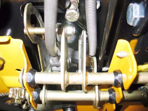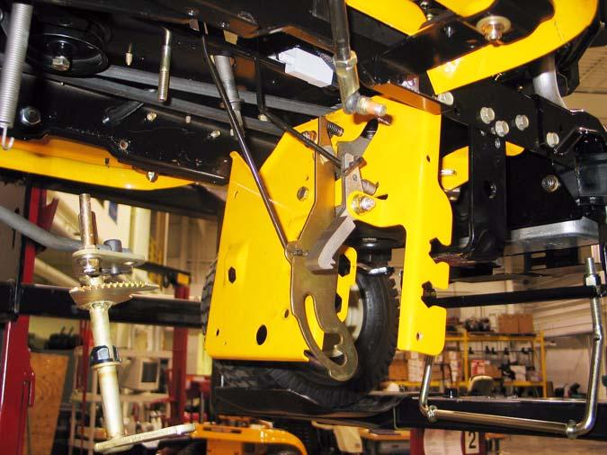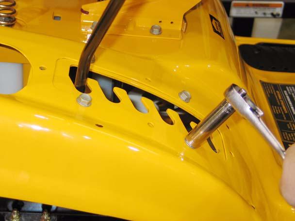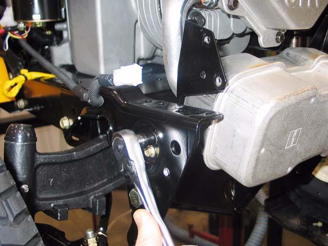
Series 1000 and 1500 31.34. As the hydro control rod is pushed rearward, it draws the cam (front) surface of the input arm upward, forcing the neutral return arm forward, applying more tension to the return spring. See Figure 31.34.
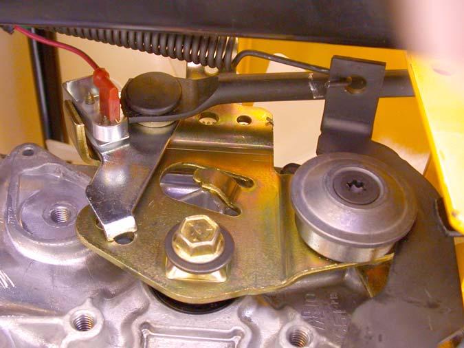
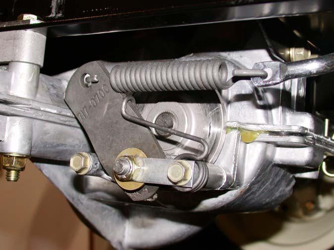
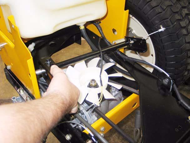
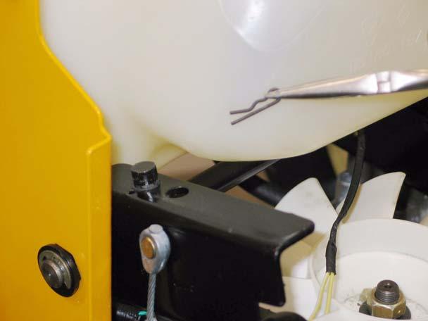
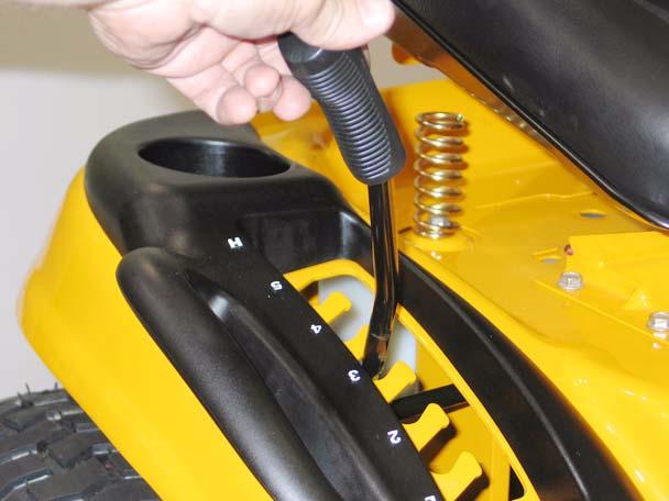
31.37. Loosen the eccentric using a 1/4” Allen wrench, and rotate it to adjust the roller up or down, as required to center the input arm in Neutral. 31.38. Tighten the socket head cap screw to lock the adjustment, and check to confirm that the adjustment is correct by repeating step 23.25. 31.39. After confirming that the transaxle is correctly adjusted:
Spring
Figure 31.34 31.35. The point that the neutral return arm draws the input arm to is determined by the position of the roller on the neutral return arm: •
If the roller is moved higher, the input arm will move in the direction that causes forward drive.
•
If the roller is moved lower, the input arm will move in the direction that causes reverse drive.
•
Adjust and reconnect the hydro control rod as described in steps 23.28 through 23.30.
•
Install the right rear wheel on the tractor, tightening the lug nuts to a torque of.
•
Lower the tractor to the ground and test the operation of the drive system in a safe area that is free of hazards, obstacles, and by-standers.
•
Install the cutting deck, test all safety features, and return the tractor to service if everything works properly.
32.
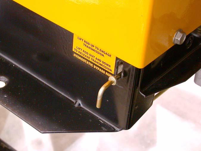
BRAKES AND BRAKE ADJUSTMENT: HYDROSTATIC GT
32.1. On hydrostatic garden tractors, most of the braking force is generated within the transaxle: when in Neutral, with the brakes released, the tractor will still be very difficult to push unless the relief valve has been opened. The brake functions mainly as a parking brake. 32.2. When properly adjusted, the brake should do two things: it should stop and hold the tractor when applied, and it should not drag when released.
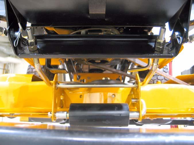
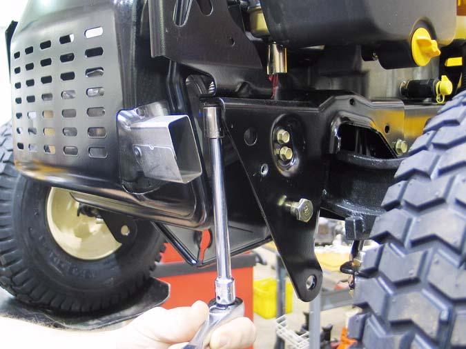
31.36. The roller is moved up or down by rotating the house-shaped eccentric that the neutral return arm pivots on. See Figure 31.36.
32.3. To check that the brakes hold the tractor: •
Open the relief valve.
•
Set the parking brake.
•
Attempt to push the tractor.
•
The wheels should skid without rotating.
•
If the brakes do not hold the tractor, the adjustment needs to be tightened or the brakes need to be repaired.
32.4. To check that the brakes do not drag:
Figure 31.36
58
•
Open the relief valve.
•
Release the parking brake.
•
Attempt to push the tractor - it should move with about 40 lbs of force. More force indicates drag.
•
If the brakes drag, they need to be adjusted or repaired.