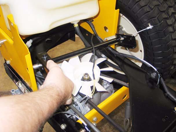
Series 1000 and 1500 23.13. The double idler pivot bracket is held to the frame by the same bolt that holds the fore-most of the two pulleys. The rear pulley can be easily removed from the bracket. It is necessary to take the fenders off to remove the front pulley or the bracket itself.
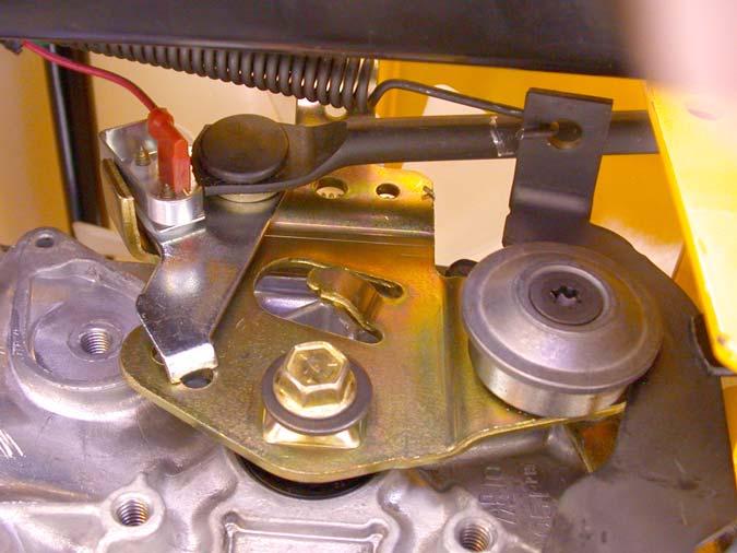
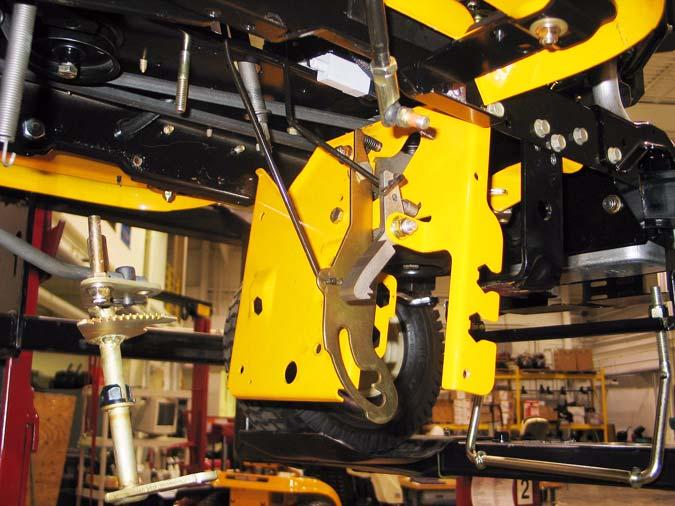
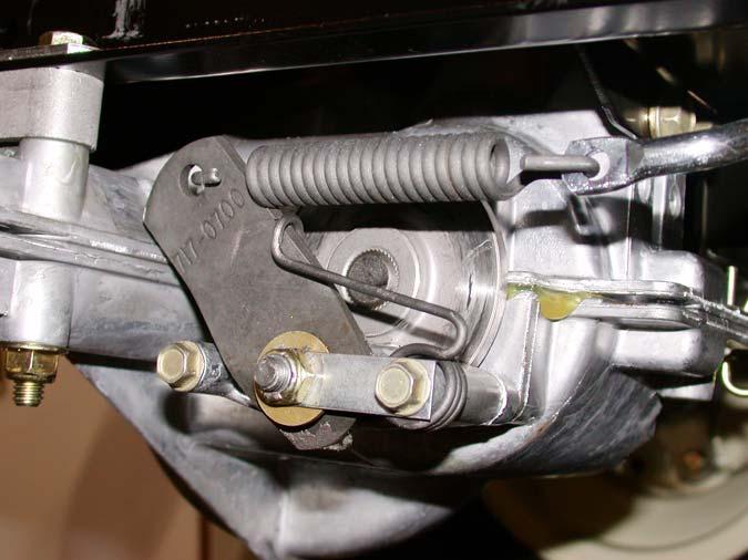
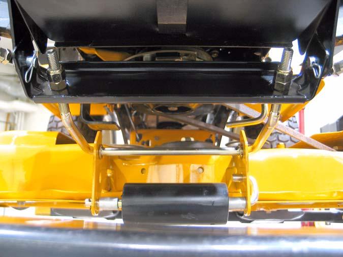
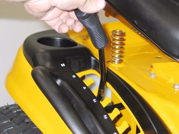
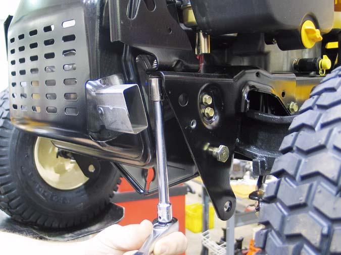
24.3. There is no adjustment to the relief valve, but full travel of the linkage should be checked if the drive system is losing power or ground speed. See Figure 24.3.
23.14. Install the drive belt by reversing the order of the removal process. •
Apply anti-seize compound to the crankshaft before installing the PTO clutch.
•
Tighten the crankshaft bolt to a torque of 38-50 ft.-lbs. on assembly.
•
Test the drive system and all tractor safety features in a clear area that is free of hazards and by standers before returning the tractor to service.
24.
DRIVE SYSTEM ADJUSTMENT: HYDROSTATIC LT
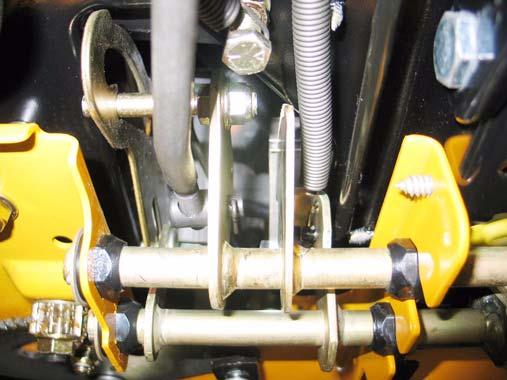
Relief valve linkage
Figure 24.3
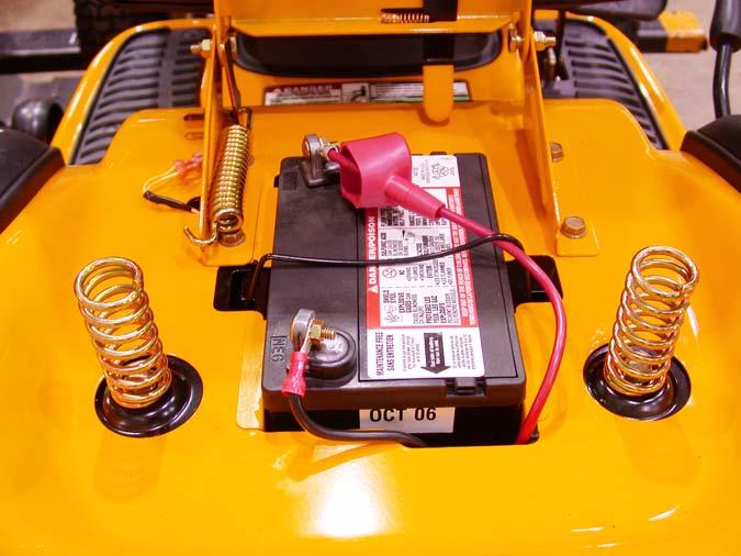
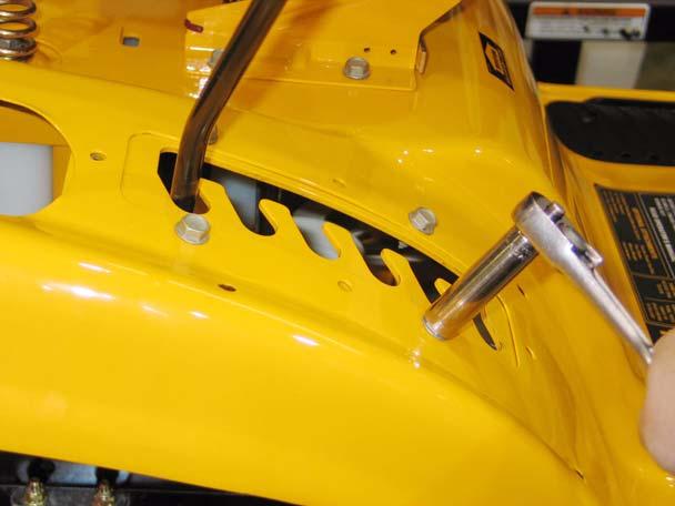
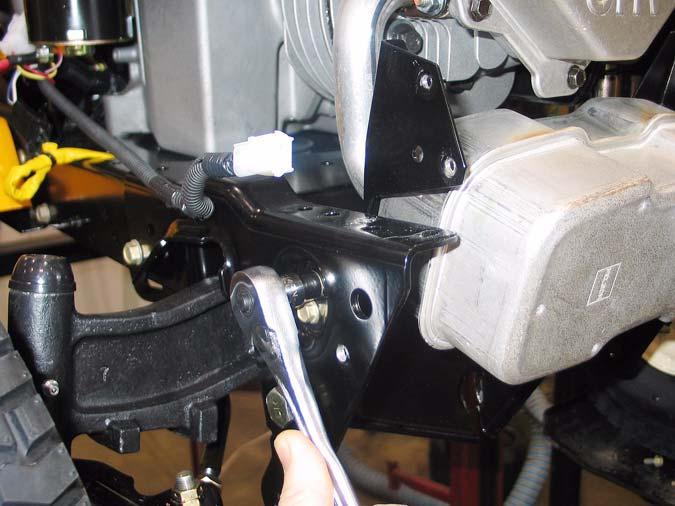
24.1. The relief valve is operated using a small rod that is visible at the bottom right corner of the rear of the tractor frame. See Figure 24.1.
24.4. Symptoms of a linkage that is out of adjustment include: •
Low ground speed in either direction with no unusual noises from the transaxle. One possible cause for low ground speed is a linkage that does not transfer all of the pedal travel to the input arm on the transaxle.
•
“Creeping” when the transaxle is in neutral position.
•
Whining or growling when the tractor is in Neutral with the brake applied.
•
The creeping and whining symptoms usually accompany one-another, indicating that the linkage is not properly centered around Neutral.
•
Low ground speed in one direction only (Forward or Reverse) may accompany whining, growling or creeping in Neutral if the linkage is out of adjustment.
•
Low ground speed, accompanied by excessive noise is likely to be an internal problem or a brake that is dragging or out of adjustment.
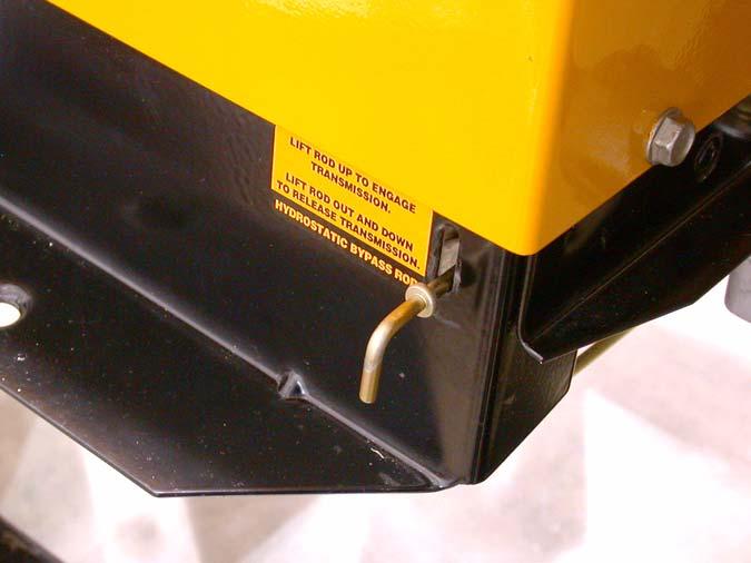
Relief valve rod
Figure 24.1 24.2. Pulling the rod out and locking it in the upper portion of the keyhole enables the tractor to be pushed, but disables the hydraulics of the drive system by opening a valve that releases the hydraulic pressure from the motor circuit.
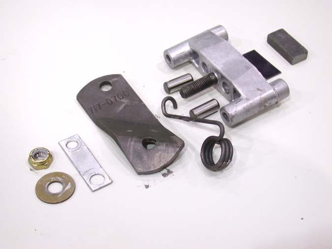
24.5. Begin linkage adjustment by inspecting the linkage. Linkages on equipment that has been in the field are usually out of adjustment because the linkage is binding, worn, bent, or tampered with. 24.6. Replace any worn or damaged parts before adjusting the linkage.
39