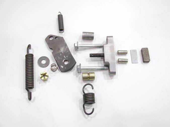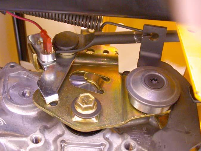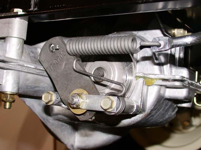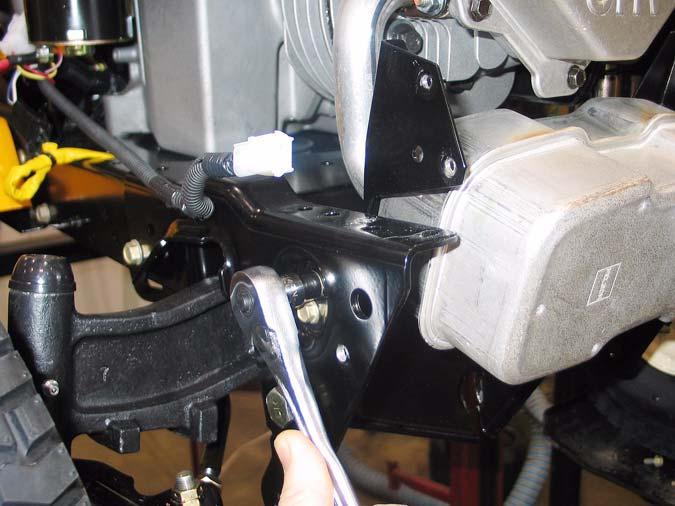
Series 1000 and 1500 19.19. A crease in the brake arm acts as a cam. At rest, the ends of the two pins ride in the peak of the crease: See Figure 19.19.
20.
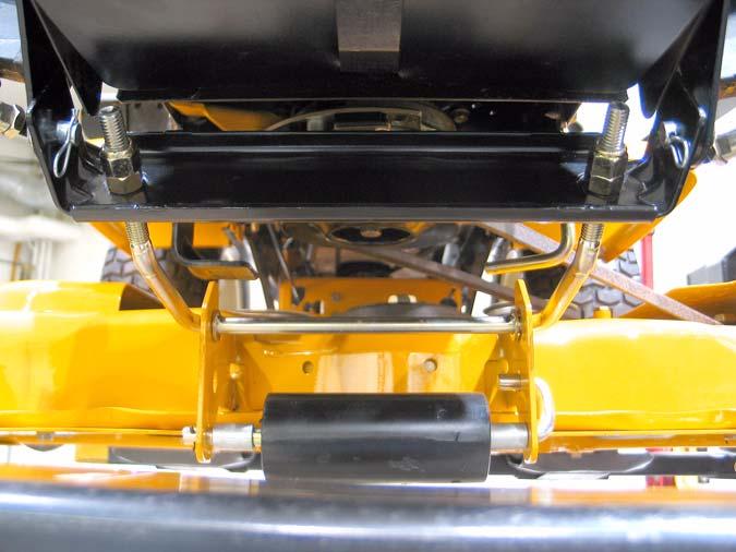
SERVICING THE BRAKE PEDAL SHAFT BUSHINGS:
•
If there is insufficient travel in the linkage to fully apply the brakes, a simple visual inspection should identify the cause.
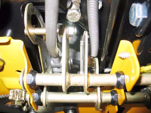
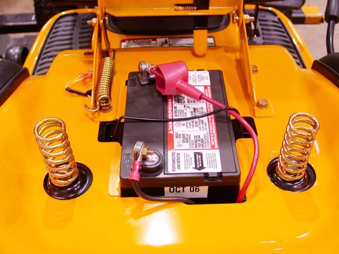
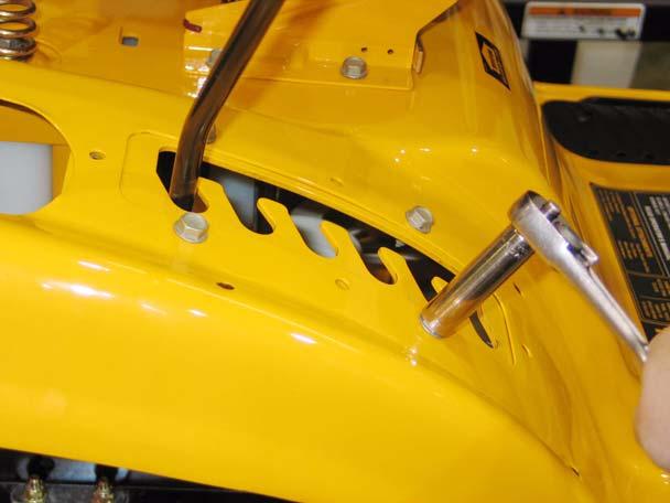
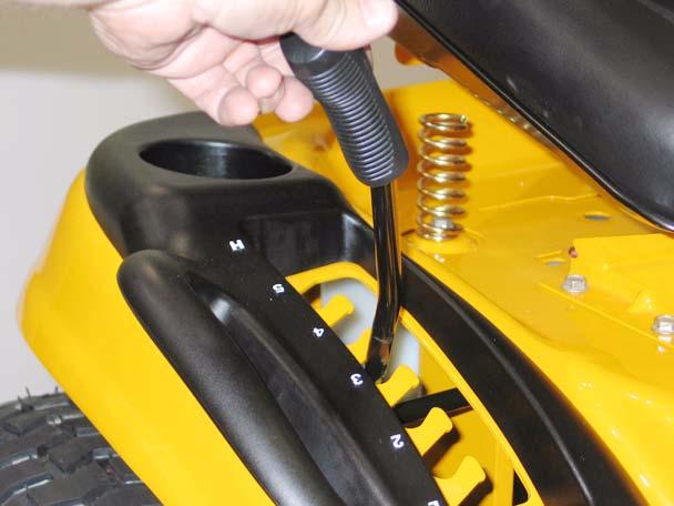
20.1. Confirm that the brake pedal is firmly attached to the pedal shaft. See Figure 20.1.
Brake Pedal
Figure 19.19 •
The brake arm pivots on a square-headed stud.
•
The two pins are forced against the backing plate when force is applied to the arm.
•
The backing plate rides between the pins and the pad, to prevent the pins from damaging the brake pad.
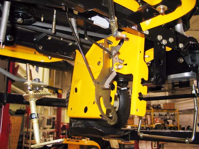
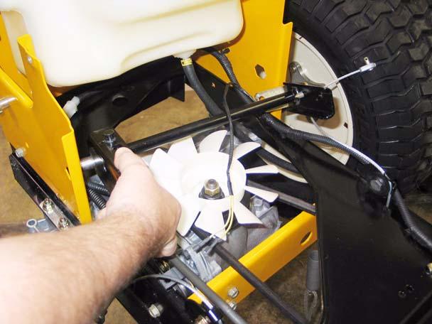
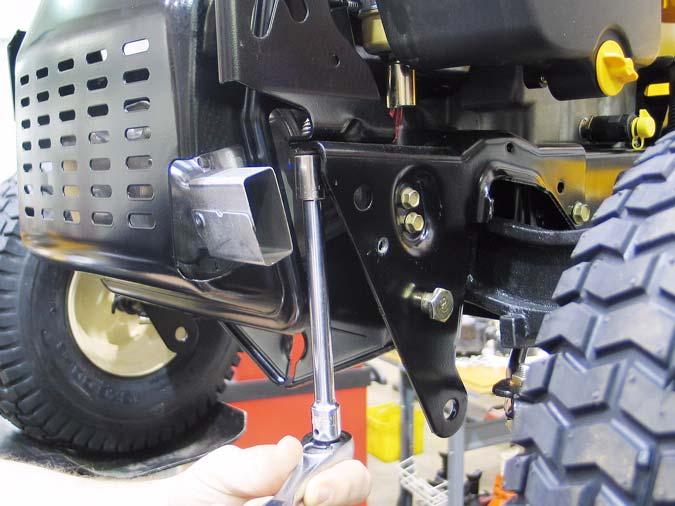
Figure 20.1 20.2. Remove the cutting deck to reach the brake pedal shaft, bushings, and bracket.
19.20. Replace the pads if they are worn. They frequently last many years unless the brakes have been dragging.
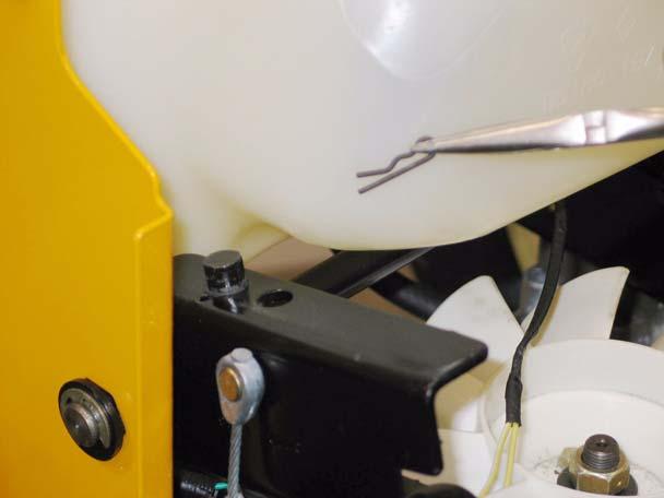
20.3. Check for excessive play in the bushings. Replace them if they are worn. NOTE: It is suggested that if any of these bushings need to be replaced, replace all of the pedal shaft bushings at this time. The speed control pedal shaft bushings are replaced in a similar manner.
19.21. Be sure the pin bores are clear of dirt and corrosion: either may cause the pins to bind and the brakes to drag. 19.22. On assembly, apply a small amount of dry graphite lubricant to the pins and the spots on the brake arm that they contact. Do not allow any lubricant to get on the brake pad. 19.23. Install the brake caliper, tightening the two nuts to 7 to 10 ft.-lbs., then check and adjust the padto-rotor clearance. 19.24. Install the rear wheel, tightening the lug nuts to a torque of 350 to 500 In.-lbs. Lower the tractor to the ground. 19.25. After any brake service is performed, test the brakes as described in steps 24.2 through 24.4, then test-drive the tractor in a safe area that is free of hazards, obstacles, and by-standers before returning the tractor to service.
32