Series 1000 and 1500 19.
BRAKE ADJUSTMENT: CVT
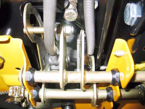
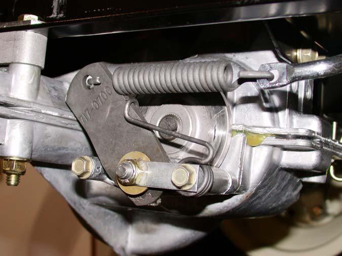
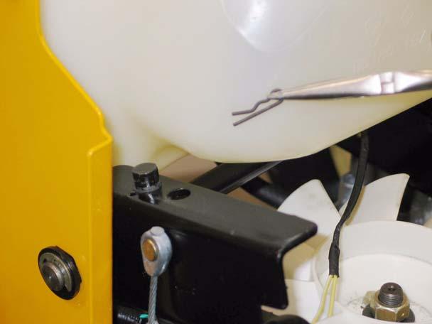
19.8. CVT-driven transaxles use a self locking nut on the brake adjustment. See Figure 19.8.
19.1. On CVT-driven lawn and garden tractors, most of the braking force is generated within the transaxle: when the drive pedal is released, the drive ratio changes, slowing the tractor. The brake brings the tractor to a complete stop, and functions as a parking brake. 19.2. When properly adjusted, the brake should do two things: it should stop and hold the tractor when applied, and it should not drag when released.
Lock nut
19.3. To check that the brakes hold the tractor: •
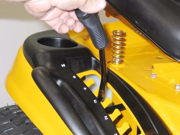
Place the gear selector in Neutral.
•
Set the parking brake.
•
Attempt to push the tractor.
•
The wheels should skid without rotating.
•
If the brakes do not hold the tractor, the brake needs to be adjusted or repaired.
Figure 19.8 19.9. Insert a .013” feeler gauge between the brake rotor and the outer brake pad. There should be slight drag on the feeler gauge.
19.4. To check that the brakes do not drag: •
Place the gear selector in Neutral.
•
Release the parking brake.
•
Attempt to push the tractor - it should move with less than 20 lbs. of force. More force indicates drag.
•
If the brakes drag, they need to be adjusted or repaired.
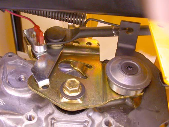
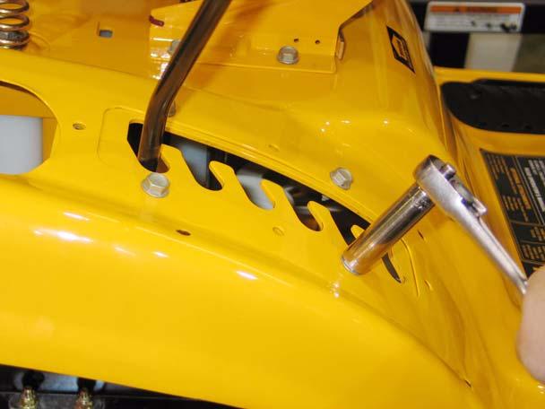
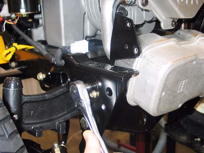
19.10. If the feeler gauge is too loose, or will not go in, brake caliper adjustment is necessary. 19.11. A 1/2” wrench will turn the adjustment nut. See Figure 19.11.
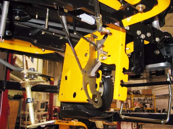
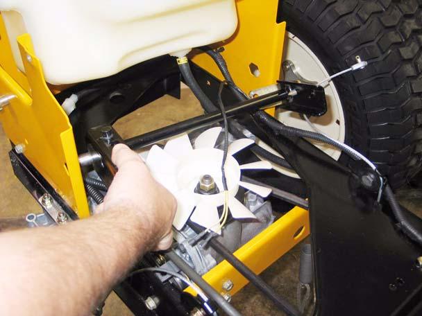
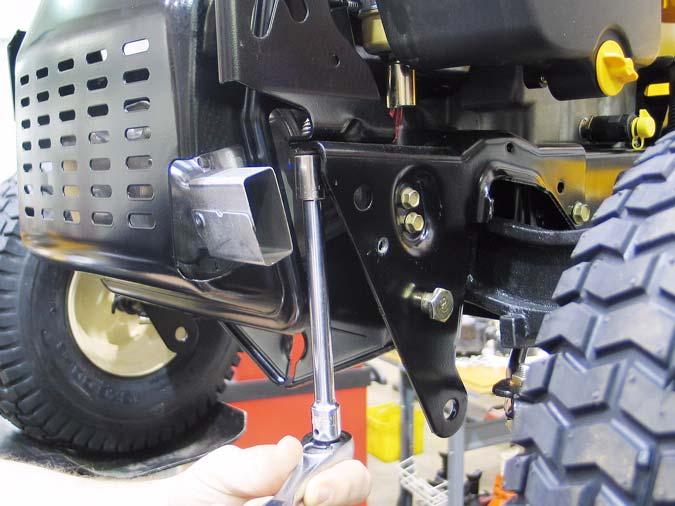
19.5. There is no linkage adjustment. All adjustment is done at the brake caliper. 19.6. To reach the brake caliper, lift and safely support the right rear corner of the tractor. 19.7. Remove the right rear wheel of the tractor using a 3/4” socket.
Figure 19.11 19.12. Tighten the nut to reduce the clearance. Loosen the nut to increase the clearance.
30