Series 1000 and 1500 bushing, it should be a dry graphite or PTFE based lube.
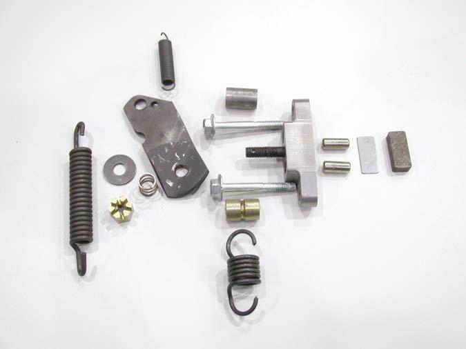
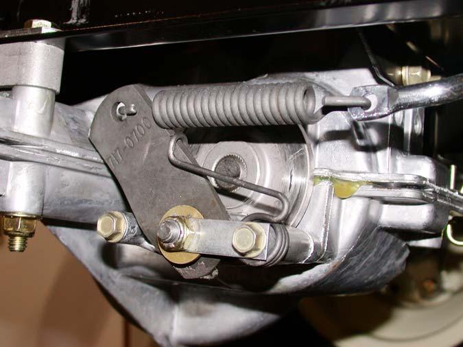
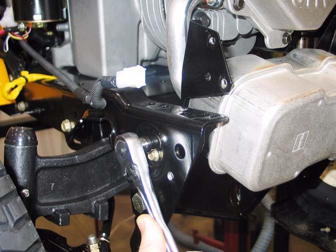
11.9. Slide the lift shaft assembly to the right, providing clearance to remove the left end of the shaft from the frame. See Figure 11.9. Lift Shaft
•
Replace the bushings an E-clips if they show signs of wear.
•
Reverse the removal process to install the lift shaft.
•
Connect the cables and install the bushings prior to connecting the tension spring between the lift shaft arm and the transaxle torque bracket.
12.
LIFT SHAFT BUSHINGS
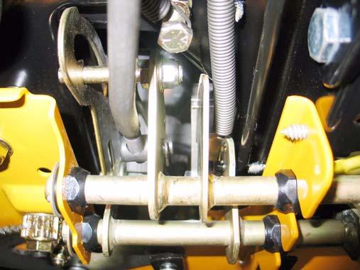
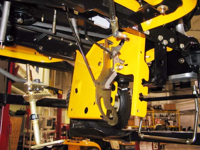
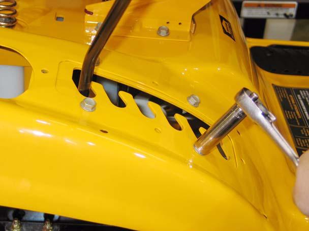
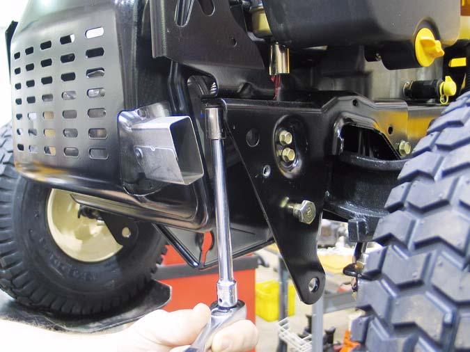
12.1. The most common item on the lift shaft assembly to require service is likely to be the bushings that support the shaft. These bushings are visible beneath the fender. See Figure 12.1.
Figure 11.9 Bushing 11.10. Slide the lift shaft back to the left to remove it from the tractor. 11.11. On the bench, relieve torsion spring pressure between the lift shaft and the lever that controls it using a length of starter rope. See Figure 11.11. Starter Rope
Torsion Spring
Figure 12.1 12.2. When performing normal maintenance that requires deck removal, inspect the lift shaft bushings while the weight of the deck is removed from them. •
These bushings are normal wear items.
•
Grasp the lift shaft and apply up and down force.
•
Watch for shaft motion within the bushings.
Figure 11.11
•
Larger decks, such as the 50” and 54” (P and K) decks will place a greater load on the bushings.
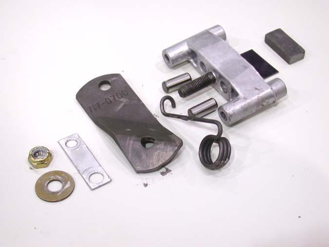
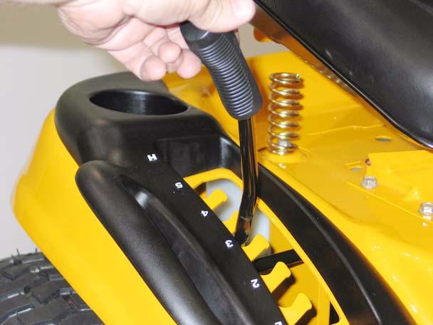
11.12. Rotate the lever to align the coined “ears” with the slots in the lift shaft arm, allowing separation of the lever from the arm.
•
Worn bushings may cause deck leveling issues.
12.3. To replace the bushings, the weight of the deck should be removed from the deck lift cable. Remove the cutting deck before attempting to remove the bushings.
11.13. Assembly notes: •
Because of the dusty environment that many mowers operate in, grease applied to this bushing may accelerate wear rather than prevent it. If any lubricant is used between the shaft and the 16