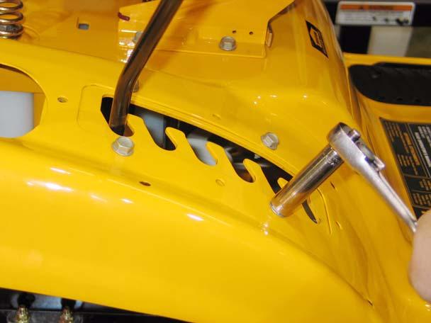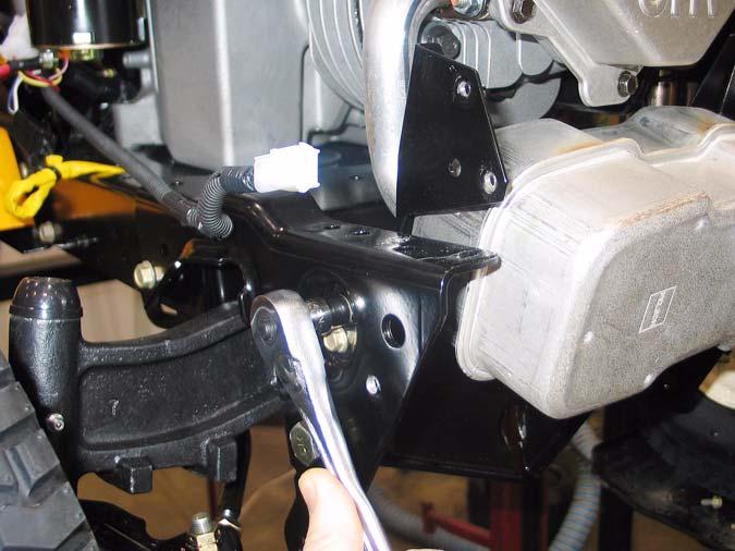
Series 1000 and 1500 5.14. Remove the two screws that were revealed by peeling-back the label. This can be done using a 3/8” wrench. See Figure 5.14.
•
When installing a large panel, start all of the threaded fasteners, then go back and tighten each after the panel is in position.
•
Test the operation of all controls and safety features in a safe place, free of obstacles and bystanders before returning the tractor to service.
6.
FUEL SYSTEM
6.1.
While the 1000 and 1500 Series tractors are built on the same frame, the fuel systems differ substantially in layout.
6.2.
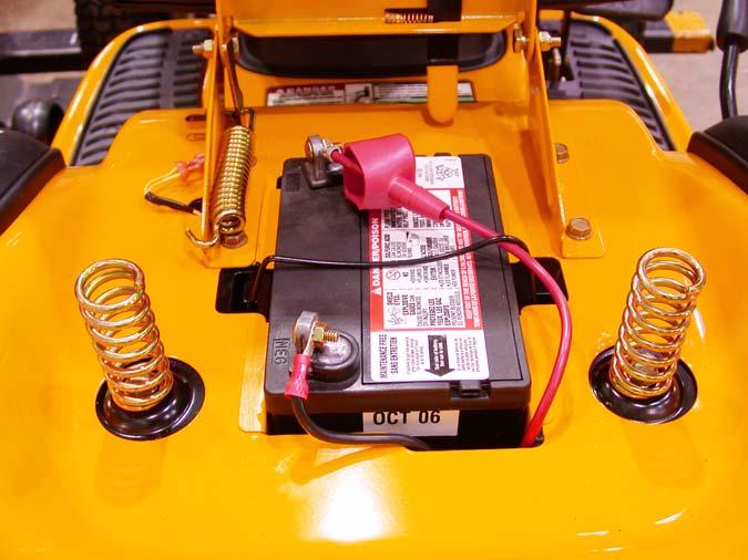
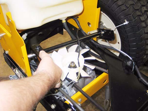
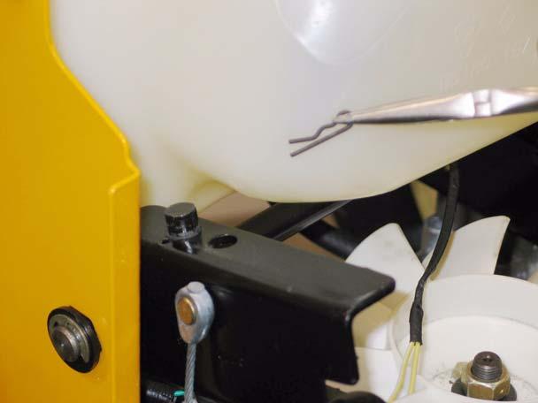
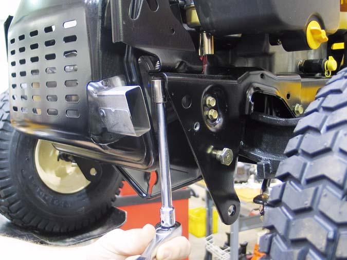
The 1000 Series tractors have the fuel tank beneath the hood, with the battery located under the seat. See Figure 6.2.
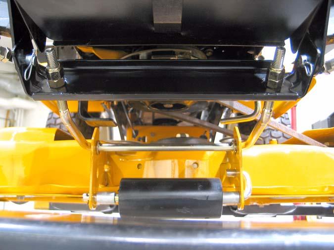
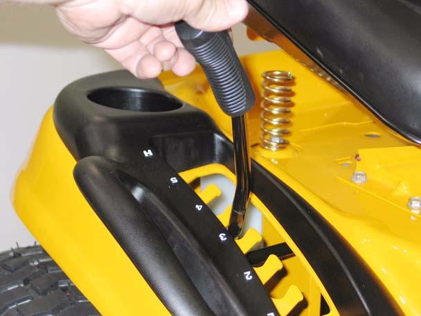
Figure 5.14 5.15. Remove the fuel filler cap. 5.16. Lift the fenders off of the tractor, maneuvering them to clear the cutting deck height control lever. See Figure 5.16.
Figure 6.2
Figure 5.16 5.17. Remove the fenders to a safe place. 5.18. Replace the fuel filler cap. 5.19. Installation notes: •
Confirm that the seat safety switch wires are accessible before securing the fender.
•
144 in-lbs is adequate tightening torque for the 5/16”-18 screws and bolts removed in this procedure. (1/2” wrench or T-40 driver)
9
6.3.
This positioning is necessary to provide easy service access to the CVT drive system used on the 1000 series tractors. The rear mounted battery, and the tray that supports it are easily removable.
6.4.
The battery of the 1500 Series tractor is located under the hood, with the fuel tank mounted under the rear fenders.