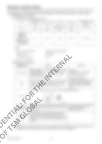
Remote Control Valve Procedures for Assembly and Disassembly of Operation Remote Control Valve 1. Maintenance Procedures (1) Required tools and tightening torque Tool
Dimensions (mm)
Part number
Part name
Screw size
Tightening torque (N•m)
22
312
Adjusting nut
M14
68.6 ± 4.9
32
302
Disk
M14
24
301
Joint
M14
Wrench Special jig (diagram in Attached diagram 2. Joint disassembly jig page 278)
47.1 ± 2.9
Other ・Sandpaper (#1000, #2000)
・White kerosene
・Whetstone
・Heat-resistant grease
・Vice
AL
・ Vapor corrosion inhibitor
RN
(2)Maintenance standards Maintenance inspection item
Standard
Remarks Conditions Primary pressure 2.94 MPa Oil viscosity 23 mm2/s
Spool
When wear on the sliding sections exceeds wear on the non-sliding sections by 10 μm or more, replace the remote control valve as one unit.
The same approximate conditions as those listed above for leak amount are expected when the condition on the left occurs.
CO US N F E ID O E F N TS TI M AL GL : F O OR BA T L H
E
IN
TE
Leak amount
When handle is in neutral 1000 cc/min or more During operation 2000 cc/min or more If either condition occurs, replace the remote control valve as one unit.
If the end section is worn by 1 mm or more, perform replacement.
Push rod
Replace the operation section disk (302) and joint Operation section (301) if there is backlash of 2 mm or more section backlash due to wear.
Operation stability
Make adjustments if the backlash is due to looseness in the tightening sections.
If abnormal noise, hunting, or a drop in primary pressure occurs and the problem cannot be resolved with "4. Causes of Trouble and Countermeasures", replace the remote control valve as one unit.
Note: It is desirable for seal materials such as O-rings to be replaced with each disassembly, but it is acceptable to reuse these after it is confirmed that they are not damaged.
RSM-13-10-001E
266 10


