4 minute read
SH210-5 Assembly and Disassembly of Swing Unit

from Sumitomo SH250-5 SH250-5LR Hydraulic Excavator Service Repair Manual WLSM2105-00W - PDF DOWNLOAD

Caution 1. Read and understand the contents of this Maintenance Manual before performing disassembly, reassembly, inspection, repair, or other such work of this product. 2. Handle this product according to the separate "Usage Cautions". 3. When removing this product from the equipment it is mounted on, stop that equipment system and wait for the surface temperature of this product to fall to about 40 ℃ or below before removing it. Working on this product while it is still hot can cause burns. Additionally, always bleed out the pressure before removing any line from this product. Removing a pressurized line can result in oil spraying out and causing burns and oil leaking. 4. Use the specialty tools and measurement instruments for disassembly, reassembly, inspection, and repair, etc. of this product. Using an inappropriate tool may result in injury or product damage. 5. Be careful of parts falling when performing disassembly, reassembly, inspection or repair, etc. of this product. This may result in injury or parts damage. 6. Do not directly touch with bare hands the machined edges or threaded sections of parts during disassembly, reassembly, inspection, or repair etc. of this product. This may result in injury. 7. Check performance after reassembly. Do not resume use unless performance is fully recovered. Using this product at a sub-par performance level may result in product damage. 8. The cautions (mark !) listed in this Maintenance Manual do not cover all possible dangers.
Always think of safety first during disassembly, inspection, reassembly, repair, or other such work.
1.Disassembly [1] Making a reference mark on the unit matching surface It is useful to place a reference mark (*1) on the matching surface of the housing (25) and ring gear (73) with paint, etc.
[2] Removal of level gauge assembly
Remove the level gauge assembly (42), cap (44) (27 mm hex diameter), and cap (34) (10 mm hex socket diameter).
[3] Gear oil draining
Loosen the drain hose (*1) end plug, and then drain the gear oil. •Gear oil cannot be reused.


[4] Removal of hose
Remove the drain hose (*1) and grease hose (*2).
[5] Removal of motor
Loosen the hexagon bolts (75) (19 mm hex diameter) and remove them along with the washers (74).
Use the make-up port (G1) to raise the motor and remove it. •Liquid packing has been applied to the matching surfaces of the housing (25) and ring gear (73), so use the notch sections (*1) in the diagram on the right to remove the motor.
This completes the disassembly.

2.Assembly [1] Liquid packing application After cleaning and degreasing the reduction gear ring gear (73) and the motor housing (25) matching surfaces, apply (*1) liquid packing (ThreeBond Co.,Ltd. "1215" gray or the equivalent) as shown in the diagram on the right.
[2] Installation of motor
Lift the motor and softly install it in the reduction gear, tighten the hexagon bolts (75) (19 mm hex diameter) holding the washers (74) in place to the tightening torque of 103 N•m. •Align the housing (25) and ring gear (73) according to the reference mark (*1) made before disassembly.


[3] Installation of level gauge assembly
Install the cap (44) (27 mm hex diameter) into the housing by tightening it to a torque of 49
N•m, and insert the level gauge assembly (42).
[4] Gear oil filling
Install a plug in the female side of the hose, and install a hose (*1) in the drain port on the side of the gear case.
Fill with gear oil (5 L) from the housing (25) gear oil fill port.
Tighten the gear oil fill port cap (34) (10 mm hex socket diameter) to the housing to a tightening torque of 49 N•m.
[5] Grease-up
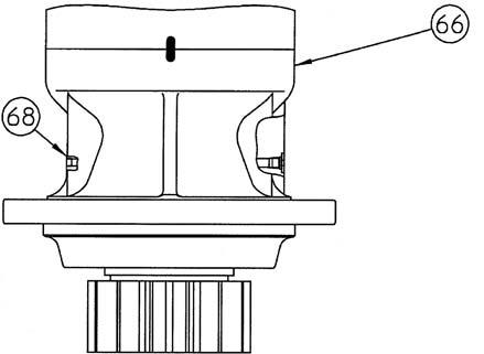
Remove the plug (68) (5 mm hex socket diameter) from the gear case (66) and inject grease (1 L) from the grease fill port. •When injecting grease, there is the possibility of the reduction gear oil seal being damaged by internal pressure, so remove the air bleed port plug before injecting grease.
Tighten the plug to the gear case to a tightening torque of 20 N•m.
After injecting grease, install the grease hose in the grease fill port.
This completes the assembly.