9 minute read
SH210-5 Assembly and Disassembly of Swing Reduction Gear

from Sumitomo SH250-5 SH250-5LR Hydraulic Excavator Service Repair Manual WLSM2105-00W - PDF DOWNLOAD

Caution 1. Read and understand the contents of this Maintenance Manual before performing disassembly, reassembly, inspection, repair, or other such work of this product. 2. Handle this product according to the separate "Usage Cautions". 3. When removing this product from the equipment it is mounted on, stop that equipment system and wait for the surface temperature of this product to fall to about 40C or below before removing it. Working on this product while it is still hot can cause burns. Additionally, always bleed out the pressure before removing any line from this product. Removing a pressurized line can result in oil spraying out and causing burns and oil leaking. 4. Use the specialty tools and measurement instruments for disassembly, reassembly, inspection, and repair, etc. of this product. Using an inappropriate tool may result in injury or product damage. 5. Be careful of parts falling when performing disassembly, reassembly, inspection or repair, etc. of this product. This may result in injury or parts damage. 6. Do not directly touch with bare hands the machined edges or threaded sections of parts during disassembly, reassembly, inspection, or repair etc. of this product. This may result in injury. 7. Check performance after reassembly. Do not resume use unless performance is fully recovered. Using this product at a sub-par performance level may result in product damage. 8. The cautions (mark !) listed in this Maintenance Manual do not cover all possible dangers.
Always think of safety first during disassembly, inspection, reassembly, repair, or other such work.
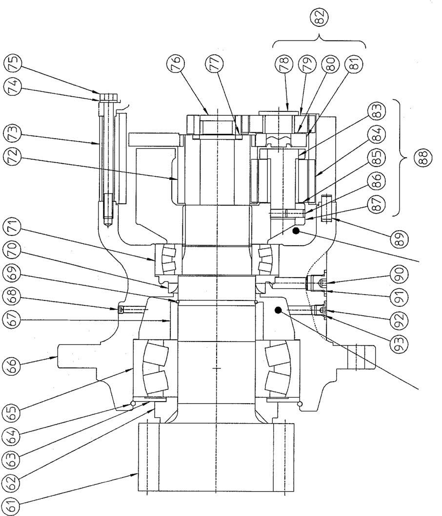
1.Disassembly [1] Remove the sun gear (76), thrust plate (77) and holder 1 assembly (82). •The opening is caulked by the press after press fitting the shaft 1 assembly (78) to holder 1 (81), so disassembly beyond this is impossible.
[2] Remove the spur tooth 4 (72) and holder 2 assembly (88).
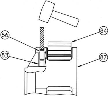
[3] Hammering the spring pin in
Hammer the spring pin (86) into the shaft 2 assembly (83). •The spring pin cannot be reused.
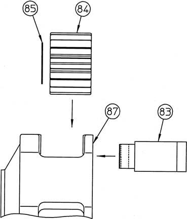
[4] Disassembly of holder 2 assembly
Remove the shaft 2 assembly (83) from holder 2 (87) while supporting the spur tooth 5 (84) by hand, and then remove the thrust plate 2 (85) and spur tooth 5. Remove the spring pin (86) from the shaft 2 assembly.

[5] Removal of ring gear
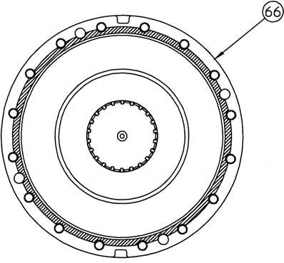
Remove the ring gear (73) from the gear case (66). Liquid packing (ThreeBond Co.,Ltd. "1215" gray) is applied to the matching surfaces of the ring gear and gear case to prevent gear oil leaking, so use the notch section (*1) on the gear case to remove the ring gear. •Place a reference mark (*2) on the matching surface of the ring gear and gear case so the attachment position can be determined during reassembly.
[6] Removal of snap ring
Use the gear case (66) notch section to remove the snap ring (64) with a flathead screwdriver.


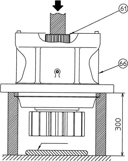
[7] Removal of shaft assembly
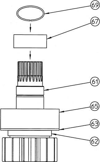
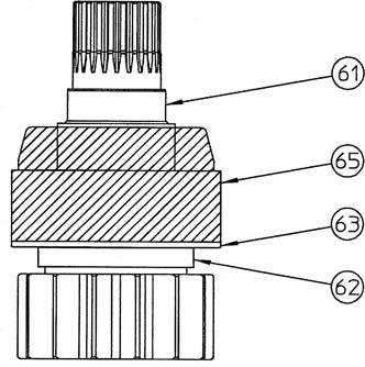
To ensure the distance that the pinion shaft (61) is removed from the gear case (66) flange section, use blocks of about 300 mm to hold up the gear case. Press the end surface of the shaft with a hydraulic press etc., and remove the pinion shaft (61), collar (62), plate (63), auto aligning roller bearing (65), collar (67), and snap ring (69) as one assembly. •Do not reuse the oil seal (70). •Place a cushion such as a rag (*1) under the pinion shaft before removing it.
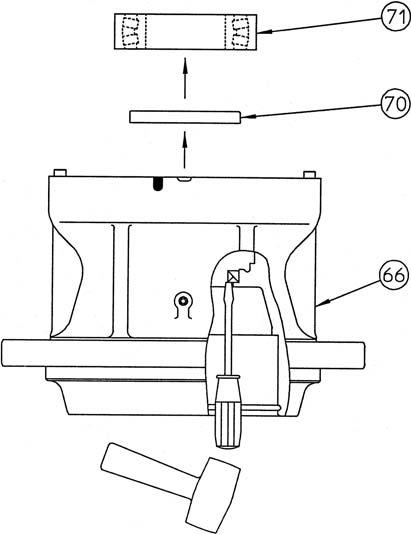
[8] Removal of auto aligning roller bearing
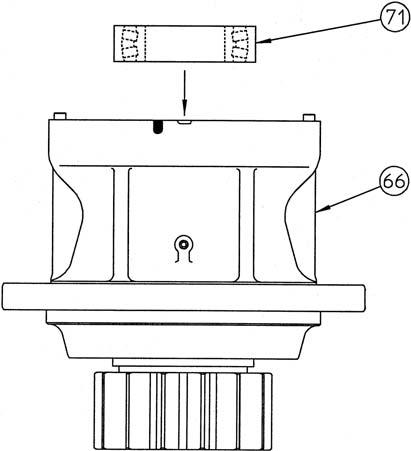
Remove the auto aligning roller bearing (71) from the gear case (66).
[9] Removal of oil seal
Strike the oil seal (70) using a screwdriver and hammer to remove it from the gear case (66). •Do not reuse the oil seal.
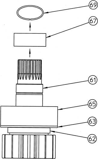
[10]Removal of collar
Remove the snap ring (69) from the pinion shaft (61) using a mark-off pin and remove the collar (67). •Do not perform disassembly of the pinion shaft assembly beyond this. If abnormalities are found amongst the parts of the pinion shaft assembly, replace the assembly.
This completes the disassembly.
2.Assembly [1] Preparation before operation Execute the following preparations before reassembly. 1) Check each part for scratches from use or from disassembly. If there are any scratches, remove them with a whetstone or sandpaper of the necessary grain, clean with cleaning oil, then dry off with an air blower. 2) Replace seal parts with new ones. [2] Installation of collar Install the collar (67) onto the pinion shaft (61) and install the snap ring (69). •Be careful to install the collar in the correct direction. (See the diagram)
[3] Grease application
Apply grease to the roller section within the auto aligning roller bearing (65) and to the outer circumference (*1).
Brand: Product equivalent to Shell Alvania EP2
Capacity:400 cc •A total of about 1 L of grease is injected into the unit.
The remaining grease is injected during unit assembly.
[4] Oil seal press fitting
Degrease the oil seal installation section of the gear case (66) and oil seal (70), and apply liquid packing (ThreeBond Co.,Ltd. "1211" white or equivalent product) to the oil seal outer diameter. Use the seal press-fit jig 1 (*1) to install the seal on the gear case. Apply a thin layer of grease to the oil seal lip section after press-fitting. •Be careful to install the oil seal in the correct direction. (See the diagram below)
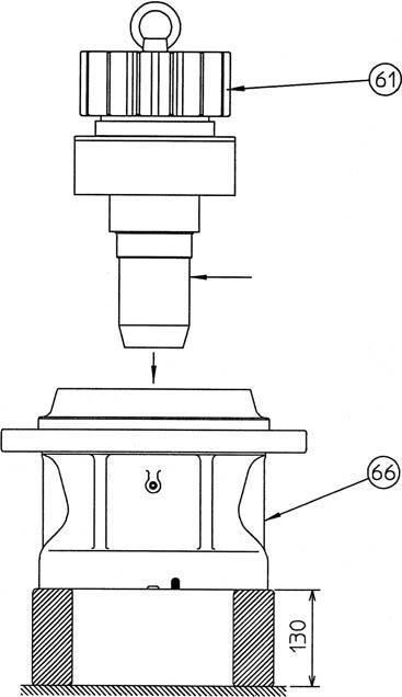
[5] Installation of pinion shaft assembly
Place the gear case (66) so that the output shaft side is pointing upwards, and screw an eyebolt into the tap hole (M8) on the end surface of the pinion shaft (61) output shaft side to lift the pinion shaft assembly and install it in the gear case.
Install the jig 2 (*1) on the spline section so that the pinion shaft spline does not scratch the oil seal. •Place an object of about 130 mm under the bottom surface of the gear case when installing the pinion shaft assembly.

[6] Installation of snap ring
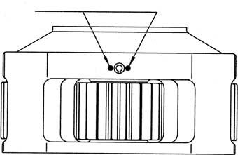
Install the snap ring (64) in the gear case (66). •To make disassembly easier later, install the snap ring with the open ends meet about 30 mm away from the notch section of the gear case.
[7] Installation of auto aligning roller bearing
Place the entire gear case (66) so that the output shaft points downwards, heat the auto aligning roller bearing (71) to "ambient temperature + 50 ℃ " and install it into the pinion shaft (61). •Be careful about burns when handling the heated auto aligning roller bearing. Be sure to wear heat-resistant gloves and do not directly touch the bearing.
[8] Application of liquid packing
Degrease the matching surface of the gear case (66). Apply liquid packing along the ring gear centering location section (*1) (ThreeBond Co.,Ltd. "1215" gray or equivalent product). Evenly apply liquid packing so that the diameter of the liquid packing extracted from the nozzle is about φ1.5.

[9] Installation of ring gear
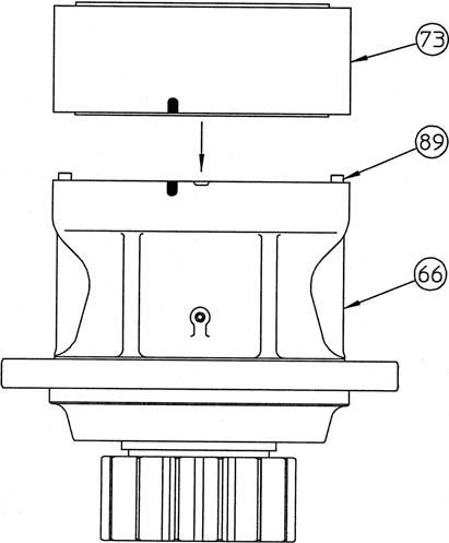
Degrease the matching surface of the ring gear (73). Align the parallel pins (89) with the ring gear parallel pin installation holes along with aligning the angles of the bolt holes, and gently install the ring gear on the gear case (66). •Align the gear case and ring gear using the reference mark made before disassembly.
[10]Assembly of holder 2 assembly
Install the spur tooth 5 (84) and thrust plate 2 (85) into holder 2 (87). Next, install the shaft 2 assembly (83) into holder 2. •At this time, apply gear oil to the inner diameter of spur tooth 5 and outer diameter of the shaft 2 assembly. •Align the pin hole of the shaft 2 assembly with the holder 2 pin hole and install.
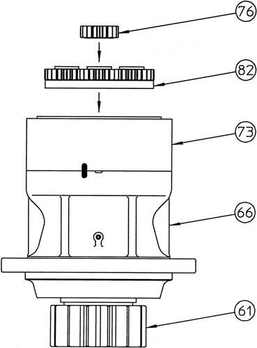
[11]Installation of spring pin
Hammer the spring pin (86) into the shaft 2 assembly (83). •Hammer the spring pin in with the crevice facing the spur tooth 5 (84) side. •After hammering in the spring pin, caulk the 2 opening locations of holder 2 (87) using a punch. (To stop the spring pin from coming out) (*1)
[12]Installation of holder 2 assembly and spur tooth 4
Insert the holder 2 assembly (88) assembled in [10] while gently engaging the assembly with the inner teeth of the ring gear (73). Additionally, insert the holder 2 assembly while turning it lightly so that spline of the pinion shaft (61) engages correctly.
Gently engage the spur tooth 5 (84) with the spur teeth 4 (72) and insert.
Make the groove on the thrust plate (77) face the spur teeth 4 side and insert it into the spur teeth 4.

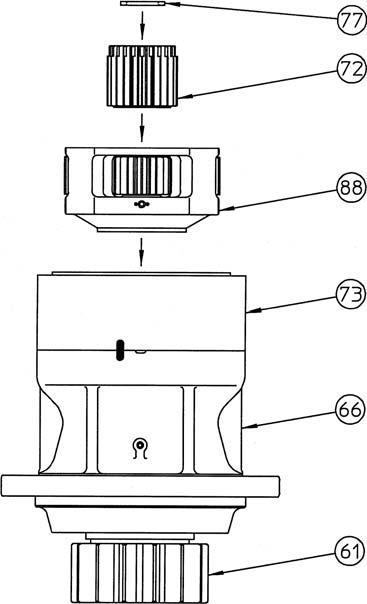
[13]Installation of holder 1 assembly and sun gear
Insert the holder 1 assembly (82) while gently engaging the assembly with the inner teeth of the ring gear (73). Additionally, insert the holder 1 assembly while turning it lightly so that teeth of the holder 1 assembly engage with the teeth of spur tooth 4 (72).
Make the groove on the sun gear (76) face the thrust plate (77) side and gently engage the groove with spur tooth 2 (79) to insert the sun gear.
[14]Assembly confirmation
Rotate the holder 1 assembly (82) by hand and check that the output shaft rotates smoothly.
This completes the assembly.
Jig 1 (For assembly of oil seal (70))
Jig 2 (For assembly of pinion shaft (61))

SH210-5 Swing reduction gear internal structure diagram
61 Pinion shaft 62 Collar 63 Plate 64 Snap ring 65 Auto aligning roller bearing 66 Gear case 67 Collar 68 Plug 69 Snap ring 70 Oil seal 71 Auto aligning roller bearing 72 Spur tooth 4 73 Ring gear 74 Lock washer 75 Hexagon bolt 76 Sun gear 77 Thrust plate 78 Shaft 1 assembly 79 Spur tooth 2 80 Thrust plate 1 81 Holder 1 82 Holder 1 assembly 83 Shaft 2 assembly 84 Spur tooth 5 85 Thrust plate 2 86 Spring pin 87 Holder 2 88 Holder 2 assembly 89 Parallel pin 90 Cap 91 O-ring 92 Cap 93 O-ring
