
9 minute read
Removal and Installation of Injector

from Sumitomo SH250-5 SH250-5LR Hydraulic Excavator Service Repair Manual WLSM2105-00W - PDF DOWNLOAD

10)Holder attachment
Engage the internal teeth of the holder (17) with the teeth of sun gear C (15) and attach sun gear C.
11)Planetary gear attachment
Attach the thrust plates (18) to the planetary gears (21).
Next, attach the needle bearings (20) to the planetary gears.
Finally, after attaching the inner races (19), join the holder (17) trunnion sections (3 locations) with the internal diameter sections of the inner races to attach the planetary gears to the holder.
Cautions: a.When attaching the thrust plates to the planetary gears, make sure the shear droop on the thrust plates created by the press is facing the holder side. b.When finally attaching the planetary gears to the holder, attach so that the internal teeth of the housing (4) engage with the planetary gear teeth. c.Be careful with the attachment directions of the planetary gears.

*1 Make the shear droop side face the holder B (17) side. *2 Thrust plate (18) attachment direction
12)Drive gear attachment
Attach the thrust plates (22) to the planetary gears (21), and attach the thrust plate (23). Insert the screws (24) with
Loctite applied in the threaded sections and tighten them to the specified torque.
Make the spline-side of the drive gear (25) face the motor section attachment side and attach the drive gear in the middle of the 3 planetary gears. Also engage the teeth of the planetary gears with the drive gear teeth.
Cautions: a.Be careful with the attachment direction of the thrust plates. b.Thoroughly clean and degrease the screw holes and threaded sections of the holder (17)


*1 Make the shear droop side face the planetary gear C (12) side. *2 Thrust plate (13) attachment direction
13)Thrust plate attachment
Measure the level difference between the housing (4) end surface and the thrust plate (23) end surface with the thrust plate selection jig, and select and attach a thrust plate (26) according to the table below.
Caution:
Align the center hole of the thrust plate with the protruding section of the drive gear (25) and attach.
14)Cover attachment
Thoroughly clean off any foreign matter from the housing (4) end surface and cover (27) matching surface.
Next, thoroughly degrease the housing end surface and cover matching surface.
Additionally, apply liquid packing to the centering location corners on the housing attachment surface-side of the cover, and align the housing screw holes and bolt openings on the cover to mount the cover on the housing.
Finally, mount the hexagon socket head bolts (28) and tighten them to the specified torque.
Level difference dimensions Appropriate thrust plate
1.20 - 0.67 20941-62306
0.66 - 0.04 20941-62307
0.03 - -0.16 20941-62308
-0.17 - -0.41 20941-62309
-0.42 - -0.80 B0841-23017
*1 Measure the level difference
15)Plug attachment
Remove the O-rings (30) attached to the plugs (29), and replace them with new
O-rings.
Next, attach plugs to the oil fill, oil drain and oil check ports (3 total) on the cover (27) and tighten them to the specified torque.
This completes assembly of the reduction gear parts. Next is assembly of motor parts. Perform assembly while referring to "[2] Assembly of motor parts".
[2] Assembly of motor parts 1) Oil seal attachment Check whether the oil seal is mounted on the flange (1-1), and use an oil seal press-fit jig to press fit the oil seal (1-12) to the flange if it is not mounted already. Cautions: a.Press fit the oil seal after applying grease to the internal diameter surface of flange oil seal press-fit section and the oil seal outside diameter section. b.Press fit the oil seal after applying grease to the lip section of the oil seal inner diameter. c.When press fitting the oil seal, push it vertically with the press. Slanting will cause damage to the oil seal outer diameter surface. d.When press fitting the oil seal, be careful not to scratch the lip section of the oil seal internal diameter. Scratching may cause oil leaking and reduction gear internal damage could occur during motor operation. 2) Piston assembly attachment Attach the springs (1-20) to the flange (1-1) holes for attaching the piston assemblies (1-7). Next, attach the piston assemblies to the flange. Cautions: a.Attach springs in the center of the hole when attaching. b.When attaching the piston assemblies, have the cylinder sections facing down. c.Before attaching the piston assemblies, apply hydraulic oil to the internal diameter surface of the flange mounting holes and the outer diameter of the piston assembly cylinder sections. d.After attaching the piston assemblies, check that the piston assemblies move smoothly.
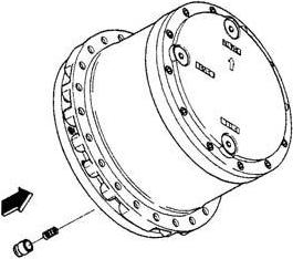
3) Steel ball attachment
Attach steel balls (1-6) to the spherical hole sections of the flange (1-1).
Caution: Before attaching the steel balls, apply hydraulic oil to the inner diameter surface of the spherical holes of the flange.
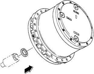
4) Shaft attachment
Use the bearing press-fit jig to press fit the ball bearing (1-8) to the shaft (1-3).
Next, attach the shaft to the center of the flange (1-1).
Cautions: a.When attaching the ball bearing, attach it vertically. b.After attaching the shaft, check that it rotates smoothly.

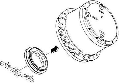
5) Swash plate attachment
Point the slanted surface of the swash plate (1-5) upwards and attach the swash plate to the flange (1-1).
Cautions: a.Attach by matching the rear surface spherical holes of the swash plate with the steel balls (1-6). b.Attach the swash plate after applying hydraulic oil to the surface of the steel balls. c.After attaching the swash plate, check that it moves smoothly. 6) Assembly of cylinder block assembly 1.Point the surface of the cylinder block (1-4-1) that slides against the valve plate (1-21) upwards and place the cylinder block on the work platform of the hand press. Point the slanted surface of the spring seat (1-4-6) down and attach it to the cylinder block. Place both the spring (1-4-7) and collar (1-4-8) on top of spring seat with the collar on top.

*1 Cylinder block attachment direction
2.Use the jig to press the top surface of the collar (1-4-8) to attach the snap ring (1-4-5).
Cautions: a.The snap ring is stiff and may come off from the snap ring pliers when the snap ring is being attached, which could cause injury. Make sure to use a jig when attaching the snap ring, and check that the nails of the snap ring pliers are in the snap ring before attachment. b.When retracting the snap ring is difficult, use the snap ring pliers that are one size bigger. c.When pressing in the collar (1-48), make the centers of the cylinder block and press align with each other. 3.Point the surface of the cylinder block (1-4-1) that slides against the valve plate (1-21) down and place the cylinder block on the work platform.
Insert the 3 pins (1-4-9) into the diagonal holes of the cylinder block (1-41).
Cautions: a.When placing the cylinder block on top of the work platform, check that there is no foreign matter on top of the work platform. b.Be careful not to scratch the surface of the cylinder block that slides against the valve plate. Scratching may cause a reduction in motor performance and early damage to the motor. c.Apply grease to the pin holes before attaching the pins.

4.Attach the retainer holder (1-4-4) to the cylinder block (1-4-1).
5.Place the side of the retainer plate (14-3) with a taper on the outer circumference down, and attach the 9 piston assemblies (1-4-2) to the retainer plate.
6.Attach the piston assemblies (1-4-2) to the cylinder block (1-4-1).
Cautions: a.Apply hydraulic oil to the 9 cylinder block piston attachment holes before attaching the piston assemblies. b.Apply hydraulic oil to the spherical surface of the retainer holder (1-44) before attaching it.
7) Cylinder block assembly attachment
Place the valve plate (1-21) sliding surface side of the cylinder block assembly (1-4) upwards, engage the internal teeth spines of the retainer holder (1-4-4) and cylinder block (1-4-1) with the external teeth spines of the shaft (1-3), and attach the cylinder block assembly to the inside of the flange (1-1).
Cautions: a.When performing attachment, check that the piston assemblies (1-4-2), retainer plate (1-4-3) and retainer holder do not come off from the cylinder block assembly. b.Before performing attachment, apply hydraulic oil to the swash plate (1-5) surface and sliding surfaces of the piston assemblies. 8) Disk plate attachment
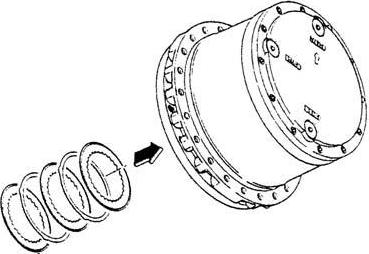
Engage the internal teeth of the disk plates (1-13) with the external teeth of the cylinder block (1-4-1) and attach the disk plates to the flange.
Also, align the arc sections on the external circumference of the friction plates (1-14) with the notch sections of the flange and attach the friction plates to the flange.
Attach in this manner with the disk plates being attached before the friction plates.
Caution: The disk plates are wet type disk. Before attachment, immerse the friction material parts in hydraulic oil and have the friction materials thoroughly absorb the hydraulic oil.

9) Brake piston attachment
Attach O-rings (1-16) and (1-17) to the brake piston (1-15).
Next, place the large bore side of the brake piston upwards and attach it to the flange (1-1).
Cautions: a.Thoroughly apply grease when attaching the O-rings. b.Attach the brake piston after using a positioning jig to align the flange base plate (1-2-1) knock pin hole and brake piston knock pin hole so that they are arranged in a straight line. c.When attaching the brake piston, apply grease to the outer circumference of the brake piston and inner diameter section of the flange. d.Push and attach the brake piston evenly all around so that it does not become slanted. If the brake piston is attached at a slant, this could cause operational problems or the O-rings to break.
10)Spring attachment
Insert the springs (1-18) into the 8 spring mounting holes on the brake piston (1-15).

11)Valve plate attachment
Place the base plate (1-2-1) on top of the work platform and press fit the bearing (1-9) in the center of the base plate using the bearing press-fit jig.
Attach the valve plate (1-21) to the base plate after checking that the knock pins (1-19) are mounted to the base plate.
Cautions: a.Place the copper alloy side of the valve plate up to attach it. b.Thoroughly apply grease to the matching surface between the base plate and valve plate to prevent the valve plate from falling. c.Be careful not to scratch the copper alloy surface of the valve plate.
