
14 minute read
Procedures for Assembly and Disassembly of Travel Remote Control Valve

from Sumitomo SH250-5 SH250-5LR Hydraulic Excavator Service Repair Manual WLSM2105-00W - PDF DOWNLOAD

When disassembling the valve, read the disassembly procedures thoroughly before following the sequence below. The numbers in the parentheses after the part names indicate codes in page300 "Attached diagram 1. Remote control valve assembly cross-section diagram". 1.Maintenance Procedures (1) Disassembly procedures [1] Preparations 1) Prepare a sufficiently spacious, solid and stable work platform so that parts will not fall or move during work. 2) Prepare tools and materials. [2] General work precautions 1) Each part has been manufactured with a high degree of precision, so be careful not to let parts bump each other or fall when handling them. 2) If parts are struck or pulled with excessive force during work because they are tight, this may cause burrs or damage which may then cause reductions in performance or oil leaking due to faulty assembly. Perform work carefully and thoroughly. 3) Rust may form on parts due to moisture or debris if the valve is left disassembled or if work is abandoned in the middle of disassembly. If work must be halted, be careful about preventing rust from forming and dust settling on parts. [3] Disassembly procedure 1) Clean the remote control valve with white kerosene. •Place plugs in each port. 2) Use shock plate to secure the remote control valve in a vise. Remove the bellows (501) from the covers (201) and remove the covers by pulling upwards.
3) Use a hexagon wrench on the hexagon socket head locking screws (423) to loosen them.
Be careful, as application of Loctite #241 makes the loosening torque high.
4) Place a round rod (φ8 mm or less) against one end of the cam shafts (413) and lightly strike it with a hammer to remove the shafts.
5) Remove the cams (420) as an assembly with the locking screws (471) and lock nuts (472) left attached.
Record the positions of the cams in relation to the covers (201).
Be careful when removing, as the push rods (214) may fly off.
6) Use a hexagon wrench on the hexagon socket head bolts (271) to loosen and remove them.
7) Remove the covers (201).
Record the positions of the covers in relation to the casing (101).
Be careful when removing, as the push rods (214) or plugs (202) may fly off due to the damping springs (336) and (337). (The plugs are only kept in the casing by the sliding resistance of the O-rings (212).)
8) Remove push rods (214) from the plugs (202).
Record the positions of the plugs in relation to the push rods.
Be careful not to scratch the surface of the push rods.
Be careful when removing, as plugs may fly off.
9) Remove the plugs (202) with the grease caps (203) and NHU packings (210) left attached.
Record the positions of the plugs in relation to the casing holes.
Be careful when removing, as the pistons (224) may fly off due to the damping springs (336) and (337).
10)Remove the pistons (224).
Record the positions of the pistons in relation to the casing holes.
11)Remove the damping springs (336) and (337) from the casing (101).
Record the positions of the damping springs in relation to the casing holes.
12)Remove the spring seatings (218) from the casing (101).
Record the position of the spring seatings in relation to the casing holes.
13)Use a magnet, etc. to remove steel balls (225).
Be careful not to lose steel balls.
14)Use pliers to remove the locking rings (221) from the casing (101).
Record the positions of the locking rings in relation to the casing holes.
Be careful when removing, as the bushings (223) may fly off due to the return springs (335).
Be careful not to scratch the inner surface of the casing.
15)Use tweezers, etc. to remove the bushings (223) from the casing (101).
Record the positions of the bushings in relation to the casing holes.
16)Remove the pressure reducing valve assemblies and returns springs (335) from the casing (101).
Record the positions of these parts in relation to the casing holes.
17)Lay the covers (201) on their sides on a level surface, place the special tool 1 against the bushings (412), and remove the bushings by lightly strike them with a hammer.
18)Secure each cam assembly in a vise, use a wrench to loosen the lock nuts (472), and remove the lock nuts and locking screws (471).
If it is not necessary to adjust, the locking screws due to backlash occurring during neutral operation, handle the cam assembly as one unit without performing disassembly.
19)For disassembly of the pressure reducing valve assemblies, place the bottom end of the spools (301) perpendicular on a level work platform, lower the spring seatings (311), and use the end of a small flathead screwdriver to remove the 2 half-circle washers 1 (215).
Be careful not to scratch the surface of the spools.
Do not lower the spring seatings by 4 mm or more. 20)Separate the spools (301), spring seatings (311), secondary pressure springs (324), washers 2 (217), and washers 3 (313).
Handle these parts as assemblies until assembly of the remote control valve.
Washers 2 are used for pre-set adjustment of the secondary pressure springs, so thickness is different for each spool assembly. Additionally, these are sometimes not used, so record the status for each assembly. 21)Remove the grease cups (203) from the plugs (202).
22)Remove the NHU packings (210) from the plugs (202). Use a small flathead screwdriver, etc. to remove the packings.
Be careful not to scratch the inner surface of the plugs.
23)Remove the O-rings (212) from the plugs (202).
24)Cleaning parts •Clean all parts by placing them in a rough cleaning container filled with white kerosene. (rough cleaning) 25)Scratching can easily occur if cleaning of parts is begun just after parts are immersed in white kerosene, so let parts sit in white kerosene until debris and grease sufficiently loosen off from the surface of parts and float to the surface.
If the white kerosene is dirty, this will encourage damage to parts and result in reduced performance after reassembly. Thoroughly manage the level of cleanliness of the white kerosene. •Clean all parts by placing them in a finish cleaning container filled with white kerosene, and thoroughly clean them up to the interior while slowly rotating them. (finish cleaning)
Use a rag to thoroughly remove white kerosene adhered to parts. 26)Do not dry parts with compressed air, as this will damage parts and cause rust to form due to debris and moisture being dispersed into the atmosphere. 27)Preventing rust on parts
Apply an anti-rust agent to each part.
Rust will form on parts if they are left as is after cleaning, and this will cause reduced performance of functions after reassemly.
(2)Assembly procedures [1] Preparations 1) As with disassembly, prepare a work platform, tools and materials.
[2] General work precautions 1) Observe the same general work precautions as with disassembly. 2) When performing assembly, remove metal fragments and foreign matter from all parts, and check that there are no burrs or nicks on parts. If there are burrs or nicks, use a whetstone to remove them. 3) As a rule, replace all O-rings and NHU packings. 4) When installing O-rings and NHU packings, be careful not to damage them. (Apply a thin layer of grease to ensure smooth installation.) 5) When installing parts, using grease is good for preventing parts from falling. 6) Tighten bolts, etc. to the torque values indicated in the assembly cross-section diagram. 7) After assembly is complete, place plugs in all of the ports to prevent entry of debris.
[3] Assembly procedures 1) Install the washers 3 (313), washers 2 (217), secondary pressure springs (324), and the spring seatings (311) onto each of spools (301) in that order. Washers 2 are used for pre-set adjustment of the secondary pressure springs, so thickness is different for each spool assembly. Additionally, these are sometimes not used. Check the status recorded during disassembly and attach parts accordingly. 2) Place the bottom end of the spools (301) perpendicular on a level work platform, push the spring seatings (311) down, and install the 2 half-circle washers 1 (215) onto the spring seatings in such a way that they are not on top of each other.
Install the washers 1 so that the sharp edge side faces up and the washer catches the head of the spool. Do not lower the spring seatings by 4 mm or more.
3) Install the return springs (335) in the casing (101).
Install them in the positions they were in before disassembly.
4) Install the pressure reducing valve subassemblies assembled in the previous steps 1) and 2) into the casing (101).
Install them in the positions they were in before disassembly.
When installing the pressure reducing valve subassemblies, be careful not to strongly strike the casing corners with the bottom ends of the spools.
5) Install the bushings (223) in the casing (101) on top of the spring seatings (311).
Install them in the positions they were in before disassembly.

6) Use pliers to temporarily install the locking rings (221) into the casing holes.
Install them in the positions they were in before disassembly.
Place them so that they are horizontal.
Be careful not to scratch the inner surface of the casing.
Place the locking rings in such a way that the sharp edge sides faces up.
7) Set the special tool 2 in each casing hole, and press in the return springs (335) and bushings (412) together until the locking rings (221) click into place in the grooves.
Slowly press in with caution so as to not scratch the inner surface of the casing.
8) Install the steel balls (225) into the bushings (412).
9) Install the spring seatings (218) into the bushings (412).
Install them in the positions they were in before disassembly.
10)Install the damping springs (336) in the casing (101).
Install them in the positions they were in before disassembly.
11)Install the damping springs (337) in the casing (101).
Install them in the positions they were in before disassembly.
Be careful that they do not become entangled with damping springs (336).
12)Install the pistons (224).
Install them in the positions they were in before disassembly.
13)Install O-rings (212) on the plugs (202).
14)Install NHU packings (210) into the plugs (202).
When installing the NHU packings, be careful of the installation direction. (See the diagram.)
Before installing NHU packings, apply a thin layer of grease.
15)Install grease cups (203) into the plugs (202).
16)Install push rods (214) into the plugs (202).
Before installing push rods, apply hydraulic oil to the rod surfaces.
Do not press the rods in strongly, as this may damage the NHU packing lip sections.
NHU packing
17)Install the push rod subassemblies assembled in the previous steps 13), 14), 15), and 16) into the casing (101).
18)Use special tool 1 on the covers (201) to press down the bushings, and lightly strike the bushings with a hammer to press fit them.
Be careful that the ends of the bushings do not stick out from within the cover.
19)Install the covers (201) on the casing (101).
Install them in the positions they were in before disassembly.
Be careful of the cover rising up due to the damping springs (336) and (337).
20)Tighten the hexagon socket head bolts (271) to the specified torque.
Tightening torque: 78.5 ± 9.8 N・m
Be careful that the covers are horizontal.
21)Temporarily install the locking screws (471) and lock nuts (472) on the cams (420).
22)Install the cams (420) on the covers (201).
Install them in the positions they were in before disassembly.
23)While holding the cams (420), insert the cam shafts (413) from the outside.
24)Apply Loctite #241 or the equivalent to the surfaces of the hexagon socket head locking screws (423).
25)Tighten the hexagon socket head locking screws (423) to the specified torque.
Tightening torque: 6.9 ± 1 N・m
26)Adjust the height of the locking screws (471) so that the top surface of the cams (420) and the bottom surface of the covers (201) are parallel, and tighten the lock nuts (472) to the specified torque after rotating the cams left and right to check if there is any neutral backlash.
Tightening torque: 33.3 ± 3.4 N・m
Even if the push rods (214) are pressed in too much by the locking screws, backlash during neutral will occur. Use caution as this may cause the sudden movement when starting the engine. 27)Tilt the cams (420) and fill the grease cups (203) of the plugs (202) with grease while applying grease to the top of the push rods (214).
For grease application and filling, use a flat object made of soft material so as to not scratch the push rod or plug surfaces.
28)After mounting the top end of the bellows (501) on the cams (420), mount the bottom end into the grooves on the covers (201).
Before mounting the bottom end of the bellows into the grooves of the covers, spray anti-rust oil on the parts within the bellows.
Be careful that the bellows are properly mounted in the grooves and not twisted, as this may reduce anti-rust and antimoisture protection.
2.Causes of Trouble and Countermeasures
It is not always easy to find where the source of trouble is located. A few problems that may sometimes occur are listed in the table below. Repair of these problems can be difficult, so see the suggested causes and solutions in the table for assistance.
The table below shows general symptoms, suggested causes and also solutions. However, the cause of machine problems are often not rooted in just a single part. Problems are often due to the relationship of one part with another. Also keep in mind that solutions other than those listed in the table may sometimes be necessary.
The table below does not include all possible causes and countermeasures. Accordingly, further investigation of problems and causes should be done by an experienced and qualified repair person, as necessary. Symptom Cause Solution
Secondary pressure is not rising.
Secondary pressure is unstable. 1. Insufficient primary pressure 2. Secondary pressure spring(s) (324) is (are) worn. 3. The gap between spool(s) and the casing is abnormally large. 4. There is backlash in the operation section.
1. Sliding parts are sticking. 2. Tank line pressure is variable. 3. Air is getting into lines. 1. Maintain primary pressure. 2. Replace it (them) with new part(s). 3. Replace spool(s) and casing assembly. 4. Disassemble and assemble or replace operation section parts. 1. Repair the sticking sections. 2. Return directly to the oil tank. 3. Perform operation several times and let out air.
Secondary pressure is high.
Damping is not working.
Damping torque is high. 1. Tank line pressure is high. 2. Sliding parts are sticking. 1. Air is gathering in the piston chamber. 2. Sliding parts are sticking. 3. Damping spring(s) (336) and/or (337) are worn. 4. The gap between piston(s) (224) and the casing is abnormally large. 5. There are check valve operation problems. 6. The piston metering hole(s) is (are) abnormally large. 1. Sliding parts are sticking. 2. Piston metering hole(s) is (are) clogged. 1. Return directly to the oil tank. 2. Repair the sticking sections. 1. Perform operation several times and let out air. 2. Repair the sticking sections. 3. Replace it (them) with new part(s). 4. Replace piston(s) and casing assembly. 5. Disassemble and adjust the check valve section(s). 6. Replace piston(s). 1. Repair the sticking sections. 2. Repair or replace piston(s).

Note 1. Apply anti-rust oil to the inside of the bellows with a spray. Attached diagram 1. Remote control valve assembly cross-section diagram
Tightening torque list Code Screw size Tightening torque 151 NPTF1/16 6.9 ± 1 N•m 271 M12 78.5 ± 9.8 N•m 423 M6 6.9 ± 1 N•m (Loctite coating) 472 M10 33.3 ± 3.4 N•m Code Part name Q'ty Code Part name Q'ty 101 Casing 1 271 Hexagon socket head bolt 2 151 Plug 2 301 Spool 4 201 Cover 2 311 Spring seating 4 202 Plug 4 313 Washer 3 4 203 Grease cup 4 324 Secondary pressure spring 4 210 NHU packing 4 335 Return spring 4 212 O-ring 4 336 Damping spring 4 214 Push rod 4 337 Damping spring 4 215 Washer 1 8 412 Bushing 4 217 Washer 2 4 413 Camshaft 2 218 Spring seating 4 420 Cam 2 221 Locking ring 4 423 Hexagon socket head locking screw 2 223 Bushing 4 471 Locking screw 4 224 Piston 4 472 Lock nut 4 225 Steel ball 12 501 Bellows 2
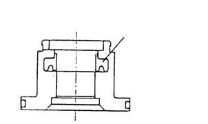
[1] Special jig 1 (for bushing removal)
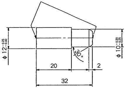
[2] Special jig 2 (for locking ring installation)

Attached diagram 2. Jig for assembly and disassembly
