
16 minute read
Removal and Installation of Supply Pump

from Sumitomo SH250-5 SH250-5LR Hydraulic Excavator Service Repair Manual WLSM2105-00W - PDF DOWNLOAD

[16]Draining reduction gear lubricating oil
Before disassembling the reduction gear section, use the tap for securing the flange (1-1) and mount two eyebolts in opposing positions to lift the reduction gear with a crane. Remove the plugs (29) in the 2 locations and drain the reduction gear lubricating oil.
Cautions: a.Prepare an oil pan before performing work. b.Do not lift to too high position when lifting with the crane. Perform work with the reduction gear at the lowest possible position (at about knee height). [17]Removal of cover
Loosen and remove the hexagon socket head bolts (28). After this, remove the cover (27).
Cautions: Use the following procedure when removing the cover. a.Liquid packing has been applied between the cover and housing (4). For this reason, it is difficult to remove the cover. Loosen the socket head bolt and strike the top and side of the cover with a plastic hammer after removing the bolt. b.Insert a flathead screwdriver in the gap between the cover and housing and remove the cover. [18]Removal of thrust plate
Remove the thrust plate (26) from the thrust plate (23) top surface.

[19]Removal of drive gear
Remove the driver gear (25).
[20]Removal of 1st stage holder assembly
Remove the 1st stage holder assembly comprising the holder B (17), planetary gears B (21), needle bearings (20), inner races (19), thrust plates (18), thrust plates (22), thrust plate (23), and screws (24).
Caution: When removing the 1st stage holder assembly, observe the following precaution. When removing the assembly, be careful of fingers getting caught.
[21]Disassembly of 1st stage holder assembly
Secure the 1st stage holder assembly with a vice and warm the screws (24) with a dryer to loosen them.
Remove the screws, thrust plate (23), thrust plates (22), planetary gears B (21), needle bearings (20), inner races (19) and thrust plates (18) from holder B (17), in that order.
Cautions: When loosening the screws, observe the following precautions. Loctite has been applied to the screws. For this reason, they do not loosen easily. If they are scratched due to being forcibly loosened, they cannot be used again. Before loosening, warm the screws sufficiently with a dryer.

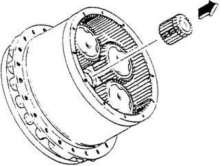
[22]Removal of sun gear C
Remove sun gear C (15).
[23]Removal of planetary gear C
Secure the flange (1-1) and loosen the bolts (14) to remove them. Next, remove the thrust plates (13), planetary gears C (12), needle bearings (11), inner races (10), and thrust plates (9), in that order.
Cautions: When loosening bolts, observe the following precautions. a.Loctite has been applied to the bolts to prevent loosening. For this reason, securely fix the flanges. b.When loosening bolts, use a tool such as a steel pipe that is long enough to reach the bolts. Straining excessively may cause back pain or injury.
[24]Disassembly of holder C
Secure the flange (1-1) and loosen and remove the bolts (8).
Holder C (6) is secured to the flange with the pins (31). Mount the removal jig from the motor side and use the press to remove holder C.
Cautions: When loosening bolts, observe the following precautions. a.Loctite has been applied to the bolts to prevent loosening. For this reason, securely fix the flanges. b.When loosening bolts, use a tool such as a steel pipe to reach the bolts. Straining excessively may cause back pain or injury.
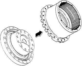
[25]Separation of flange and housing
Mount the jig on the outer circumference brim end surface of the housing (4), and then press the flange (1-1) with the press to separate the housing and flange.


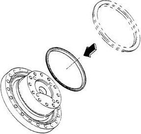
[26]Removal of floating seal
Raise the outer circumference of the floating seals (2) with a flathead screwdriver and remove the floating seals.
[27]Parts storage
This completes the entire disassembly.
When storing disassembled parts, place parts in plastic bags in a cool, dark and dry location after cleaning the parts and applying anti-rust oil.
If parts are stored in a hot, moist location, rust will develop even if anti-rust oil is applied.
Also store them in a way so that dust does not collect on them.

4.Maintenance Standards (1)Motor parts maintenance standards Table 6 shows maintenance standards for motor parts. Check each part according to the motor parts maintenance standards in Table 6. When a permissible limit has been exceeded or is near being exceeded, perform part repair or replacement according to repair and solution procedures. Table 6. Motor parts maintenance standards
Applicable part Inspection and measurement location Permissible limit value Repair, solution procedure Piston assemblies (1-4-2) 1.Shoe sliding surfaces
2.Piston outer circumferences
3.Piston outer diameters and cylinder block (4-1) bore inner diameters 0.8 a degree of roughness Or the surface is rough and there is scratching of at least 0.02 mm deep. 1.2 a degree of roughness Or the surface is rough and there is scratching at least 0.02 mm deep. Gap 0.060 mm
4.Shoe bore backlash 0.4 mm of backlash
Cylinder block (1-4-1) 1.Surface that slides against the valve plate
0.8 a degree of roughness Or the surface is rough and there is scratching at least 0.02 mm deep. 2.Bore inner diameter 1.6 a degree of roughness Or the surface is rough and there is scratching at least 0.02 mm deep.
3.Bore inner diameter and piston assembly (4-2) outer diameter Gap 0.060 mm
Cylinder block (1-4-1) 3.Shaft bonding section spline
Diameter between parts 38.749 mm Diameter of measurement pin φ3.333 (V1=2.80) mm Or breaking damage is occurring. Valve plate (1-21) 1.Sliding surface 0.8 a degree of roughness There is scratching at least 0.02 mm deep on the sliding surface. Or seizing is occurring. There is abnormal wear on the sliding surface.
Retainer plate (1-4-3) Retainer holder (1-4-4)
1.Sliding surface 0.8 a degree of roughness There is scratching at least 0.02 mm deep on the sliding surface. Or seizing is occurring. Swash plate (1-5) 1.Sliding surface 0.8 a degree of roughness There is abnormal wear or scratching least 0.02 mm deep on the sliding surface.
2.Steel ball mounting section spherical hole
3.Steel ball mounting section spherical hole 1.6 a degree of roughness There is scratching at least 0.02 mm deep on the ball surface or the surface is rough. Ball depth 14.5 mm Lap the shoe sliding surface(s) (#1000) If the scratching cannot be removed, replace the cylinder block assembly (4).
Replace the cylinder block assembly (4).
Lap the sliding surface (#1000) If the scratching cannot be removed, replace the cylinder block assembly (4).
Replace the cylinder block assembly (4).
Replace the cylinder block assembly (4).
Lap the sliding surface (#1000) If the scratching cannot be removed, replace the valve plate (22).
Replace the retainer plate and retainer holder.
Lap the sliding surface (#1000) If the scratching cannot be removed, replace the valve plate (22).
Replace the swash plate.
Applicable part Inspection and measurement location Permissible limit value Repair, solution procedure Shafts (1-3) 1.Oil seal sliding surface outer diameters
2.Cylinder block bonding section spines
3.Drive gear bonding section spines 1.6 a degree of roughness Aside from the oil seal lip sliding imprint, there is scratching at least 0.02 mm deep or the surface is rough. Over-pin diameter 47.380 mm Diameter of measurement pin φ3.00 mm Or breaking damage is occurring. Diameter between parts 30.498 mm Diameter of measurement pin φ3.33 mm Or breaking damage is occurring. Replace the shaft(s).
Break piston (1-15) 1.Appearance dimensions Height 38.2 mm Replace the brake piston.
2.Sliding surface 2.5 a degree of roughness 3.Appearance There is scratching at least 0.02 mm deep or the surface is rough.
Disk plates (1-13) 1.Appearance dimensions Thickness 3.2 mm Replace the disk plate(s).
Ball bearing (1-8) Ball bearing (1-9)
Piston assemblies (1-7)
Plunger assembly (1-2-2) 2.Appearance There is deep scratching or friction material is peeling off. 1.Rotation surface Flaking or pressure imprinting is occurring. 2.Operation There are rotation abnormalities (abnormal noises, rotation unevenness)
1.Shoe sliding surfaces 1.6 a degree of roughness Or the surface is rough and there is scratching at least 0.02 mm deep.
2.Piston outer circumferences
3.Piston outer diameters and flange holder (1-1) inner diameters 1.2 a degree of roughness Or the surface is rough and there is scratching at least 0.02 mm deep. Gap 0.040 mm
4.Shoe bore backlash 1.0 mm of backlash 1.Plunger outer diameter
2.Plunger outer diameter and base plate inner diameter 0.8 a degree of roughness There is scratching at least 0.02 mm deep or the surface is rough. Gap 0.060 mm Replace the ball bearing.
Lap the shoe sliding surface(s) (#1000) If the scratching cannot be removed, replace using the flange holder kit.
Replace using the flange holder kit.
Replace using the base plate kit.
Applicable part Inspection and measurement location Permissible limit value Repair, solution procedure Base plate (1-2-1) 1.Plunger assembly (2-2) mounting hole
2.Base plate inner diameter and plunger outer diameter 3.Spool assembly (211) mounting hole
4.Base plate inner diameter and spool outer diameter 0.8 a degree of roughness There is scratching at least 0.02 mm deep or the surface is rough. Gap 0.060
0.8 a degree of roughness There is scratching at least 0.02 mm deep or the surface is rough. Gap 0.060 mm Replace using the base plate kit.
Spool assembly (1-2-9) 5.Relief valve assembly free piston sliding and seat sections 1.Spool outer diameter
2.Spool outer diameter and base plate inner diameter
Free piston (1-2-7-9)
1.Surface that slides against the base plate and seat section Housing (1-2-7-1) 1.Surface that slides against free piston (outer diameter) Spring (1-4-7) 1.Appearance dimensions There is scratching at least 0.02 mm deep or the surface is rough.
0.8 a degree of roughness There is scratching at least 0.02 mm deep or the surface is rough. Gap 0.060 mm
There is scratching at least 0.02 mm deep or the surface is rough.
There is scratching at least 0.02 mm deep or the surface is rough. Free length 61.0 mm
2.Appearance There is deformation and scratching on the coil surface.
Springs (1-18) 1.Appearance dimensions Free length 39.0 mm Replace using the base plate kit.
Replace using the relief valve assembly.
2.Appearance There is deformation and scratching on the coil surface.
Springs (1-20) 1.Appearance dimensions Free length 41.5 mm
2.Appearance There is deformation and scratching on the coil surface.
Springs (1-2-4) 1.Appearance dimensions Free length 48.5 mm
2.Appearance There is deformation and scratching on the coil surface.
Spring (1-2-10) 1.Appearance dimensions Free length 28.3 mm
Each O-ring and oil seal 2.Appearance There is deformation and scratching on the coil surface. During disassembly Replace each O-ring and oil seal.
(2)Reduction gear parts maintenance standards
Table 7 shows maintenance standards for reduction gear parts. Check each part according to the reduction gear parts maintenance standards in Table 7. When a permissible limit has been exceeded or is near being exceeded, perform part repair or replacement according to repair and solution procedures.
Table 7. Reduction gear maintenance standards
Applicable part Inspection and measurement location Permissible limit value Repair, solution procedure
Planetary gears (21) Tooth thicknesses Across 6 teeth 66.649 mm
Tooth surfaces There is pitching on 10 % or more of the tooth surface or breaking damage is occurring. Inner diameters Flaking is occurring on the inner diameter surface.
Needle bearings (20) Roller rotation surfaces
Inner races (19) Outer diameter surfaces Flaking is occurring on the surface.
Flaking is occurring on the surface.
Drive gear (25) Tooth thickness Across 3 teeth 29.908 mm
Tooth surface There is pitching on 10 % or more of the tooth surface or breaking damage is occurring. Spline section Over-pin diameter 38.989 mm Diameter of measurement pin φ3.00 mm Or breaking damage is occurring.
Holder (17) Tooth thickness of internal tooth
Diameter between parts 66.742 mm Diameter of measurement pin φ7.00 mm Or breaking damage is occurring. Sun gear (I5) Tooth thickness Across 4 teeth 41.371 mm
Planetary gears (12) Tooth surface There is pitching on 10 % or more of the tooth surface or breaking damage is occurring. Tooth thicknesses Across 6 teeth 65.662 mm
Tooth surfaces There is pitching on 10 % or more of the tooth surface or breaking damage is occurring. Inner diameters Flaking is occurring on the inner diameter surface.
Needle bearings (11) Roller rotation surfaces Flaking is occurring on the surface.
Inner races (10) Outer diameter surface Flaking is occurring on the surface. Replace the planetary gear(s).
Replace the planetary gear(s), needle bearing(s) and inner race(s).
Replace the drive gear.
If replacing the drive gear(s), inspect the shaft at the same time.
Replace the holder.
Replace the sun gear.
Replace the planetary gear(s).
Replace the planetary gear(s), needle bearing(s) and inner race(s).
Applicable part Inspection and measurement location Permissible limit value Repair, solution procedure
Housing (4) Tooth thickness Diameter between parts 330.449 mm Diameter of measurement pin φ7.000 mm Replace the housing.
Tooth surface There is pitching on 10 % or more of the tooth surface or breaking damage is occurring. Shim (5) During disassembly Replace the shim. Flange (1-1) 2-speed piston hole inner diameter and piston assembly outer diameter Gap 0.040 mm Replace using the flange kit.
2-speed piston hole inner diameter
1.2 a degree of roughness Or the surface is rough or there is scratching at least 0.02 mm deep. Thrust plate (26) Thickness Plate thickness 3.3 mmPlate thickness 2.5 mm Plate thickness 2.9 mmPlate thickness 2.0 mm Plate thickness 2.7 mm Or there is deep scratching on the sliding surface. Replace the thrust plate.
Angular bearings (3) Ball rotation surfaces Flaking is occurring. Replace the angular bearing(s). Operation Abnormal noise or unsmooth rotation occurs with rotation.
Floating seals (2) Sliding surfaces There is deep scratching that may cause oil leaking. O-rings Cracking is occurring on the surface.
Replace the floating seal(s). When doing more disassembly beyond this, because oil leaking may occur due to the seal ring slide imprints not matching up of reused seals when reassembly is done, replace these seals before reassembly. Each O-ring During disassembly Replace each O-ring.
5.Assembly of Motor (1)Precautions before motor assembly Begin motor assembly only after thoroughly reading the precautions below. [1] When performing assembly, always wear protective devices such as a helmet, goggles and safety shoes. [2] Use the specified tools when performing assembly. [3] To prevent injuries during disassembly, prepare a waist-high, stable work platform to perform work on. [4] The motor comprises high-precision parts. For this reason, foreign matter adhering to parts can be damaging. Motor assembly should be done in an inside space without dust, and mud and dirt should be prevented from adhering to parts. [5] The motor comprises high-precision parts. For this reason, dents and scratching on part surfaces can be damaging. Be very careful when handling parts during assembly and do not create any dents or scratching. [6] Be sure to repair any damage discovered during disassembly, and prepare replacement parts before beginning assembly. [7] Remove metal fragments and foreign matter from all parts, and check that there are no burrs or nicks on parts before beginning assembly. If there are burrs or nicks, use a whetstone to remove them. [8] When performing assembly, apply clean hydraulic oil to each sliding and rotating section before assembly. [9] Thoroughly degrease areas where Loctite and liquid packing is used, and remove oil and water before assembly. [10]As a rule, replace all seal parts such as O-rings and backup rings with new parts. [11]Be careful not to damage O-rings and backup rings during assembly. When assembling Orings and backup rings, apply a small amount of grease for assembly. [12]It is recommended that petroleum jelly or grease be used to prevent parts from falling during assembly. [13]Tighten each type of bolt at the connection sections to the tightening torque indicated in Table 5 in 3. (2). Tightening torque should be controlled with a torque wrench. [14]After assembly is complete, plug all ports leading into the motor to prevent dirt from entering.
(2)Assembly procedures
Perform assembly by observing the precautions listed in Section 1 and following the procedure indicated below. [1] Assembly of reduction gear section 1) Attaching floating seal to flange After confirming the items below concerning the floating seals (2), use the floating seal installation jig to attach the floating seals to the flange (1-1). Confirmation items: a.Check that there is no dirt adhered to the floating seal mounting surfaces on the flange. b.Thoroughly degrease the floating seal mounting surfaces on the flange. c.Check that there is no dirt adhered to the O-ring surfaces on the floating seals. d.Thoroughly degrease the O-ring surfaces on the floating seals. 2) Attaching angular bearing to housing Use the press-fit jig or press to press fit the angular bearings (3) to the housing (4).

3) Attaching floating seal to housing
After confirming the items below concerning the floating seals (2), use the floating seal installation jig to attach the floating seals to the housing (4).
Confirmation items: a.Check that there is no dirt adhered to the floating seal mounting surface on the housing. b.Thoroughly degrease the floating seal mounting surface on the housing c.Check that there is no dirt adhered to the O-ring surfaces on the floating seals. d.Thoroughly degrease the O-ring surfaces on the floating seals. 4) Attaching the housing to the flange
After confirming the items below, use a crane to attach the housing to the flange so that the floating seal (2) section of the flange (1-1) is aligned with the floating seal section of the housing (4).
Confirmation items: a.Check that there is no dirt adhered to the seal ring sliding surfaces of the floating seals. b.Apply reduction gear lubricating oil or hydraulic oil all around the seal ring sliding surfaces of the floating seals (1-2). c.When attaching the flange holder and housing (1-6), attach them after checking that the axis center is aligned.

5) Shim thickness selection
Select the precompression adjustment shim (5) thickness according to the following procedure. 1.Use the shim thickness adjustment jig to press the inner ring end sections of the angular bearings (3) with a load of 2.94 kN. 2.Measure the H level dimensions at this time for the angular bearings inner ring end surfaces and flange end surface. 3.Measure the h level dimensions of the holder (6). 4.Select a shim and install it so that the shim thickness is appropriate to the dimensions (H-h).
Cautions: a.Do not reuse shims. b.Be sure to perform this procedure properly. If precompression adjustment is not done properly, reduction gear damage could occur during operation. c.Clean the measurement surfaces.
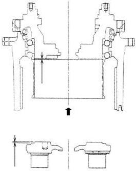
1 Press load of 2.94 kN 2 H dimensions 3 h dimensions
