35 minute read
Procedures for Assembly and Disassembly of Control Valve

from Sumitomo SH250-5 SH250-5LR Hydraulic Excavator Service Repair Manual WLSM2105-00W - PDF DOWNLOAD

1.Disassembly (1)Cautions for disassembly [1] On a level ground, with the main machine horizontal, bring all the operating machines into contact with the ground. Check that the machine is in such a state that it will not travel or swing on its own. Then stop the engine and bleed out the pressure from each actuator.
[2] Bleed the oil pressure from the tank. [3] Clean well around the location to be disassembled and keep foreign matter from getting into the valve during disassembly. [4] Identify disassembled parts with shipping tags to show their position for re-assembly. [5] Do not reuse any disassembled seals (O-rings, backup rings). Replace them with new ones. [6] The spool was selected to fit with the valve housing and sleeve, so do not replace the spool. (2)Disassembly procedure (The reference numbers are from the parts list.) a)Removal of long cap and pull out of main spool [1] Loosen the hexagon socket head bolts (74) (8 mm hex socket diameter) for the caps (8) (9 locations) and the cap (9) (1 location) and remove them. When pulling out the spool only, do not loosen the M6 screws on the plate except for the hexagon socket head bolts (75) (4 locations) and (94) fastening the plate assemblies. [2] Loosen and remove the plugs (91) (19 mm hex diameter) attached to the ports as necessary. [3] Remove the O-rings (7) (one in each section) from the plate assemblies (10) and (11). [4] Pull out each spool from the valve housing still in the sub-assembly state.
[5] Loosen and remove the hexagon socket head bolts (75) (8 mm hex socket diameter) and hexagon socket head bolts (94) (5 mm hex socket diameter) those fastens the plate assemblies (10), (11), (28) and (29) to the housing.
Remove the plate assemblies still in the assembly state. Do not disassemble them. [6] Loosen and remove the plugs (91) (19 mm hex socket diameter) as necessary. [7] Remove the O-rings (7) and (41) from the valve housings (1) and (13).
Caution Do not replace a valve assembly or disassemble a valve with pressure remaining in the system. This would be dangerous. High-pressure oil might spray out or parts might suddenly come out. For disassembly, bring the bucket to the ground and adequately bleed out any pressure in the circuits.
Caution 1. When pulling out the spool, be careful not to cause any dents or scratches. 2. Identify each spool with a shipping tag so that there will be no mistake about their positions when they are re-assembled.
[8] Disassembly of spool assembly
1) Loosen the spool assembly (2) - (6) and (14) - (17) spool ends (8 mm hex socket diameter) and disassemble the spring seat and spring. 2) The spools in spool assemblies (3), (4), (6) and (14) have poppets, springs, plugs, and filters in the spools, but do not disassemble them unless necessary. When disassembly is required, heat up the outer edge of the spool to break down the adhesive on the thread section, then remove the plug. When assembling, always replace O-rings and backup rings with new ones. b)Disassembly of arm 1 parallel-tandem spool, neutral cut spool section [1] Loosen and remove the hexagon socket head bolts (78) (5 mm hex socket diameter) for the caps (18) and (86). [2] Remove the O-ring (23) from the cap (18). Remove the O-rings (65) from the housing (1). [3] Pull out the spools (19) and (84) from the valve housing still in the sub-assembly state. [4] Disassembly of spool assembly
1) Loosen the spool (19) spool end (22) (5 mm hex socket diameter) and disassemble the spring seats (20) and spring (21). c)Disassembly of arm regeneration release valve section (Sub-parts in the assembly are expressed as [main number - sub-number].)
[1] Loosen and remove the plug (24) (32 mm hex diameter) and remove the O-ring (25). [2] Remove the spring (26) and spool (27-1) from the sleeve (27-2). [3] Pull out the sleeve (27-2) from the valve housing. [4] Remove the piston (27-3), O-ring (30), and backup rings (31) from the sleeve (27-2).
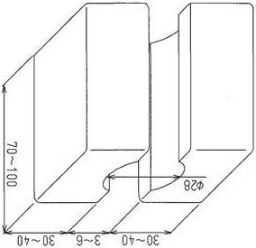
Caution 1. In order to avoid damaging the outer edge of the spool, sandwich the spool with wooden blocks (as in the diagram on the right) and fasten with a vise before starting the work. 2. Since adhesive is applied to the spool end thread section, heat up the outer edge of the spool thread section to break down the adhesive. 3. Heat the spool to 200 - 250 ℃ . Heat until the spool end loosens easily immediately after the heating. 4. If overheating occurs, replace the spring with a new one.
(Wooden blocks for spool assembly/disassembly)
Caution 1. In order to avoid damaging the outer edge of the spool, sandwich the spool with wooden blocks for assemble (as in the diagram) and fasten with a vise before starting the work. 2. Since adhesive is applied to the spool end thread section, heat up the outer edge of the spool thread section to break down the adhesive. 3. Heat the spool to 200 - 250 ℃ . Heat until the spool end loosens easily immediately after the heating. 4. If overheating occurs, replace the spring with a new one.
Caution 1. When removing the plug, pressure left within can make parts fly out dangerously. 2. Slowly loosen the plug to check that there is no resistance due to residual pressure, then disassemble.
d)Disassembly of load check valve section
[1] Loosen and remove the hexagon socket head bolts (75) (4 locations in each section, 8 mm hex socket diameter) for the flanges (37) (6 locations) and (61) (1 location). The (61) flange has a different shape from the other flanges, so keep it separate from (37). [2] Remove the springs (35), poppets (34) and (51) and O-rings (36) from the valve housing. Remove the arm 2 (E-E cross section) poppet (59), spring (60), and sleeve (58). [3] Loosen and remove the hexagon socket head bolts (75) (8 mm hex socket diameter) for the flanges (52) (2 locations) . [4] Remove the spacers (53) from the valve housing and remove the O-rings (54) and backup rings (55) from the spacers (53). [5] Remove the springs (35) and poppets (34) from the valve housing. [6] Loosen and remove the plugs (72) (8 mm hex socket diameter). (D-D cross section) [7] Remove the springs (33) and poppets (32) from the valve housing. [8] Loosen and remove the plugs (72) (8 mm hex socket diameter). (D-D cross section) [9] Remove the spacer (57), springs (33), and poppets (32) from the valve housing. [10]Loosen and remove the plug assemblies (92) (36 mm hex diameter). (P4 section, H-H cross section) [11]Loosen and remove the hexagon socket head bolts (74) (4 locations, 8 mm hex socket diameter) for the flange (43) . [12]Remove the spring (45), poppet (44), and O-rings (36) from the valve housing. [13]Loosen and remove the plug (46) (27 mm hex diameter) and remove the O-ring (47). (HH cross section) [14]Remove the spring (48) and poppet (49) from the valve housing. e)Disassembly of antidrift valve section (Sub-parts in the assembly are expressed as [main number - sub-number].)
[1] Loosen and remove the hexagon socket head bolts (74) (4 locations in each section, 8 mm hex socket diameter) for the antidrift valve assemblies (67) (2 locations). [2] Remove the O-rings (36) and (41) from the valve housing. [3] Remove the springs (39) and poppets (38) from the valve housing. [4] Disassembly of antidrift valve assembly
1) Loosen and remove the plug assembly (67-14) (38 mm hex diameter) and remove the
O-rings. 2) Remove the piston (67-3), spool (67-4), and spring (67-6). 3) Loosen and remove the plug (67-14) (12 mm hex diameter). 4) Remove the sleeve (67-5) and poppet (67-2) from the body and remove the O-rings (67-8) and (67-9), backup rings (67-10) and (67-11) from the outer edge of the sleeve. 5) Remove the spring seat (67-13) and spring (67-7) from deep in the hole.
Caution 1. When removing the plug, pressure left within can make parts fly out dangerously. 2. Slowly loosen the plug to check that there is no resistance due to residual pressure, then disassemble.
Caution 1. When removing the antidrift valve assembly, pressure left within can make seals and other parts fly out dangerously. 2. Slowly loosen the hexagon socket head bolt to check that there is no resistance due to residual pressure, then disassemble.
Caution 1. If parts inside the antidrift valve are disassembled with the antidrift valve installed in the valve housing, pressure left within can make parts fly out dangerously. 2. Slowly loosen the plug assembly (67-12) to check that there is no resistance due to residual pressure, then disassemble.
f) Disassembly of relief valve
[1] Loosen and remove the overload relief valve (69) (32 mm hex diameter). [2] Loosen and remove the main relief valve (68) (32 mm hex diameter). [3] Loosen and remove the relief valve assemblies (70) (2 locations, 32 mm hex diameter). Remove the O-rings (70-5) and (70-8). g)Disassembly of option section [1] Loosen and remove the hexagon socket head bolts (75) (8 mm hex socket diameter) for the caps (88) (2 locations) and remove the O-rings (89). [2] Loosen and remove the plug assemblies (93) (2 locations, 24 mm hex diameter) and remove the O-rings and backup rings. h)Disassembly of straight travel signal control valve [1] Remove the hexagon socket head bolts (83) (5 mm hex socket diameter) and remove the body assembly (42). [2] Loosen and remove the plug assembly (42-5) (5 mm hex socket diameter) and remove the O-ring. [3] Pull out the spools (42-2) and (42-3) and spring (42-4). [4] Loosen the orifice plug (42-7) (36 mm hex diameter) and remove it from the body (42-1). i) Disassembly of other plugs [1] Loosen and remove the plug assemblies (71) (10 mm hex socket diameter) and remove the O-rings. [2] Loosen and remove the plug assemblies (72) (8 mm hex socket diameter) and remove the O-rings. [3] Loosen and remove the orifice plug (40) (5 mm hex socket diameter). (D-D cross section) [4] Loosen and remove the plug assemblies (92) (36 mm hex diameter) and remove the Orings. [5] Loosen and remove the plug assemblies (73) (6 mm hex socket diameter) and remove the O-rings. j) Disassembly of add-on section [1] Loosen and remove the hexagon nuts (97) (4 locations, 22 mm hex diameter). [2] Remove the outlet housing (95). Execute Steps [3] - [5] below as necessary. [3] Remove the spool section assembly (98) and remove the matching surface O-rings (9810) and (98-11). [4] Remove the inlet section assembly (99) and remove the matching surface O-rings (99-3) and (99-4). [5] Remove the spool section assembly (111) and remove the matching surface O-rings (110-10) and (110-11). [6] Remove the main unit body matching surface O-rings (56) and (64). [7] Loosen the tie rods (96) and remove them from the main unit valve housing (1). (Use a pipe wrench.)
Caution 1. When removing the relief valve, loosen and remove the main unit installation section plug. 2. Do not loosen the set pressure adjustment plug or lock nut. 3. Doing so would be dangerous because the set pressure changes if the set pressure adjustment plug turns.
Caution When removing the add-on section, be careful not to cause any dents, scratches, or the like on matching surfaces. Any dents, scratches, or the like on matching surfaces have a danger of allowing oil to leak from those surfaces and causing malfunction. Also, be careful not to let any foreign matter enter the oil path. Such foreign matter has a danger of the spool sticking due to biting of the spool sliding section or a load check seat defect making the actuator run wild or stop disabled.
k)Disassembly of valve housing union bolt
[1] Loosen and remove the hexagon socket head bolts (77) (8 locations, 14 mm hex socket diameter). Tightening torque: 166 - 177 N•m [2] Remove the valve housing matching surface O-rings (65) and (66). (3)Cleaning
Completely clean all the disassembled parts with clean mineral oil.
Dry with compressed air and place each part on clean paper or vinyl for inspection. (4)Inspection
Inspect all surfaces of each part for burrs, scratches, gouges, and other defects. [1] Inspect the valve housing load check seat surface for scratches, gouges, and also for debris, dents, rust. Repair any minor scratches with an oilstone. [2] Check that there are no scratches, dents, etc. on the outer edge of the spool. Repair any small scratches with an oilstone. [3] Sliding parts must all move easily. Also, all grooves and paths must be free of foreign matter. [4] If a spring is broken or extremely deformed or worn, replace it. [5] If relief valve operation is poor, inspect according to "(9) Troubles and countermeasures Relief valve". [6] Replace all O-rings and backup rings from disassembled parts. [7] After removing caps and plugs, check for any paint fragments around the body opening or plug seating surface. (If paint fragments were to get inside the valve, they could jam up or clog up the valve, resulting in operation defects and oil leaks.)
Caution 1. Do not disassemble the union bolt (77) unless necessary. 2. If such disassembly is necessary, place the main unit on a flat table to do the work. 3. Prepare the replacement O-rings (65) and (66).
(5)Assembly 1)Cautions for assembly a)Cautions for O-Ring handling [1] Do not use any O-ring with a molding defect or damage caused by handling. [2] Apply enough grease or hydraulic oil to the O-ring and the section where it is mounted so that it can be mounted smoothly. [3] Do not stretch an O-ring so far that this causes permanent deformation. [4] When assembling an O-ring, be careful not to roll the O-ring into place. (If an O-ring is mounted twisted, it is difficult for it to naturally recover to its normal state and that twist causes oil leaks.) b)Cautions for spool handling [1] Excessive torque on thread sections causes spool operation defects, so always tighten to just the specified torque. [2] Be careful to assemble all spools, springs, and spool ends in the same combinations as before disassembly. c)Adhesive application method (for male thread section and female thread section of parts requiring adhesion) [1] Cleaning (degreasing) Either use vapor degreasing with acetate, ether or clean with an alkali cleaning agent. [2] Drying Dry the surface to be glued, either by blowing clean air on it or letting it dry naturally. Inadequate drying reduces the effectiveness of the adhesive. [3] Applying the adhesive Apply a small amount of adhesive (equivalent to Loctite #638) to the first 2 - 3 threads at the entrance of the spool female threads. At this time, install being careful that the application section does not touch the spring seat.
[4] Adhesive hardening time
In order to ensure the hardening of the adhesive, after fastening the spool end, leave the part out in the air for the following period of time. - Ambient temperature around 22 ℃ : 8 hr. or longer - Ambient temperature around 40 ℃ : 3 hr. or longer - Ambient temperature around 5 ℃ : 24 hr. or longer
Caution Do not use "Loctite Primer T" hardening accelerator. It causes insufficient adhesion strength.
Caution If the parts are not left out in the air for the above period, adequate adhesive strength may not be achieved.
2)Procedure for assembly of sub-assembly
a)Assembly of spool assembly (main spool) [1] Apply adhesive to the thread sections of the spools (2) - (6), (14) - (17) and assembly the spring seat, spring, and spool end. [2] Sandwich the spool with the wooden blocks (the same ones used for disassembly), fasten in place with a vise, then tighten the spool ends to the specified torque. Tightening torque: 20 - 22 N•m [3] For spools (3), (4), and (14), insert the poppets and springs from the end opposite from the spool end, then apply adhesive to the thread sections of the plugs with the O-rings and backup rings mounted, and tighten. Also, for each spools (5), the plug with filter is mounted at this location. Tightening torque: 10 - 12 N•m
b)Assembly of arm 1 parallel-tandem spool assembly [1] Apply adhesive to the thread sections of the spool (19) and assemble the spring seats (20), spring (21), and spring end (22). [2] Sandwich the spool with the wooden blocks (the same ones used for disassembly), fasten in place with a vise, then tighten the spool ends to the specified torque. Tightening torque: 19 - 22 N•m
c)Assembly of neutral cut spool assembly [1] Apply adhesive to the thread sections of the spool (84-1) and assemble the spring seat (84-2), spring (84-3), and spring end (84-4). [2] Sandwich the spool with the wooden blocks (the same ones used for disassembly), fasten in place with a vise, then tighten the spool ends to the specified torque. Tightening torque: 19 - 22 N•m
d)Assembly of antidrift valve assembly [1] Assemble the O-rings (67-8) and (67-9) and backup rings (67-10) and (67-11) into the grooves on the outer edge of the sleeve (67-5).
[2] Insert the poppet (67-2) and spool (67-4) in the sleeve hole. Be careful to assemble the spool in the correct direction.
Caution Before starting the assembling, check the quantity of each part, the installation location, the required tools, etc.
Caution 1. Be careful not to apply so much adhesive that it drips into the spool. 2. Be careful not to tighten any spool end with excessive torque. Excessive torque there would deteriorate spool operation. 3. There are two types of spring. Be careful to assemble each in its correct location. (only boom 2 different)
Caution 1. Be careful not to apply so much adhesive that it drips into the spool. 2. Be careful not to tighten any spool end with excessive torque. Excessive torque there would deteriorate spool operation.
Caution 1. Be careful not to apply so much adhesive that it drips into the spool. 2. Be careful not to tighten any spool end with excessive torque. Excessive torque there would deteriorate spool operation.
Caution 1. Be careful to assemble O-rings and backup rings in the correct locations. 2. If they are assembled backwards, there is a danger of an O-ring being damaged and the drop of the actuator from its own weight increasing.
[3] Install the spring seat (67-13) at the small-diameter section at the tip of the poppet, mount on the spring (67-7), and insert into the body (67-1) together with the sleeve.
[4] Screw the plug (67-14) into the body (67-1) and tighten it. Tightening torque: 78 - 88 N•m [5] Assemble the spring (67-6) and piston (67-3) on the plug (67-14). [6] Tighten the plug assembly (67-12) with O-ring mounted to the body (67-1). Tightening torque: 147 - 157 N•m 3)Procedure for assembly of control valve main unit a)Assembly of relief valve
[1] Screw in and tighten the main relief valve (68). Tightening torque: 78 - 88 N•m [2] Screw in and tighten the overload relief valves (69) (6 locations) at each section. Tightening torque: 78 - 88 N•m [3] Screw in and tighten the relief valve assemblies with O-rings mounted (70) (2 locations). Tightening torque: 103 - 113 N•m b)Assembly of load check valve [1] Mount the O-rings (36) in the arm 1 section (E-E cross section), Boom 1 and 2 sections (F-F cross sections), swing section, and bucket section (G-G cross sections) and assemble the poppets (34) and springs (35). Mount the flanges (37) and tighten with the hexagon socket head bolts (75). Tightening torque: 58 - 64 N•m For the arm 2 section (E-E section), assemble the sleeve (58), poppet (59) and spring (60), mount the flange (61), and tighten with the hexagon socket head bolts (75). Tightening torque: 58 - 64 N•m [2] Mount the O-rings (36) in the travel section (I-I cross section) and assemble the poppet (51) and springs (35). Tighten the flanges (37) with the hexagon socket head bolts (75). Tightening torque: 58 - 64 N•m [3] Assemble the poppets (34) and springs (35) on the common check section (J-J cross section), then insert the spacers (53) with the O-rings (54) and backup rings (55) mounted. Tighten the flanges (52) with the hexagon socket head bolts (75). Tightening torque: 39 - 44 N•m
[4] Mount the O-rings (36) in the option section (H-H cross section) and assemble the poppet (44) and spring (45). Mount the flange (43) and tighten with the hexagon socket head bolts (74).
Tightening torque: 58 - 64 N•m [5] Assemble the poppet (49) and spring (48) in the travel section (H-H cross section).
Screw in and tighten the plug (46) with O-ring (47) mounted.
Tightening torque: 107 - 117 N•m
Caution Apply grease to the poppet seat so that the spring and spring seat can be installed correctly on the poppet seat.
Caution 1. When installing the relief valve, be sure to tighten the main unit installation section plug. 2. Do not tighten the set pressure adjustment plug or lock nut. 3. Doing so would be dangerous because the set pressure changes if the set pressure adjustment plug turns.
Caution 1. Be careful to assemble O-rings and backup rings in the correct locations. 2. If they are assembled backwards, there is a danger of an O-ring being damaged and causing external leaks.
[6] Assemble the poppets (32) and springs (33) in the arm 1 parallel-tandem section (D-D cross section). Screw in and tighten the plug assemblies (72) with O-rings mounted. Tightening torque: 73 - 79 N•m [7] Assemble the poppets (32), springs (33), and spacer (57) in the arm 2 parallel-tandem section (D-D cross section). Screw in and tighten the plug assemblies (72) with O-rings mounted. Tightening torque: 73 - 79 N•m c)Assembly of antidrift valve [1] Mount the O-rings (36) and (41) on the antidrift valve installation surfaces in the arm 1 section (E-E cross section) and boom 1 section (F-F cross section). [2] Assemble the poppets (38) and springs (39). [3] Install the antidrift valve assemblies (67) (2 locations) and tighten with the hexagon socket head bolts (74). Tightening torque: 39 - 44 N•m d)Assembly of option section [1] Install the caps (88) (2 locations) with O-rings (89) mounted and tighten with the hexagon socket head bolts (75). Tightening torque: 58 - 64 N•m [2] Screw in and tighten the plug assemblies (93) (2 locations) with O-rings and backup rings mounted. Tightening torque: 78 - 88 N•m e)Assembly of arm regeneration release valve [1] Mount the O-ring (30) and backup rings (31) (2 locations) in the sleeve (27-2). [2] Assemble the piston (27-3) and spool (27-1) in the sleeve and insert into the valve housing. [3] Put the spring (26) into the plug (24) with O-ring (25) mounted, then screw into the valve housing and tighten. Tightening torque: 103 - 113 N•m f) Assembly of arm 1 parallel-tandem spool [1] Assemble the spool (19) in the sub-assembly state into the valve housing.
[2] Mount the cap (18) with O-ring mounted (23) and tighten with the hexagon socket head bolts (78). Tightening torque: 8.8 - 10.8 N•m g)Assembly of neutral cut spool [1] Assemble the spool assembly (84) into the valve housing.
[2] Mount the O-rings (65) into the housing and tighten the cap (86) with the hexagon socket head bolts (78).
Tightening torque: 8.8 - 10.8 N•m
Caution After inserting the spool, slide it to check for any sticky or rough feeling.
Caution After inserting the spool, slide it to check for any sticky or rough feeling.
h)Assembly of main spool [1] Mount the O-rings (7) and (41) on the valve housing cap matching surface. [2] Assemble the spool assemblies (2) - (6), (14) - (17) in the sub-assembly state into the same location as before disassembly.
[3] Install the plate assemblies (28) and (29) and tighten the hexagon socket head bolts in the order (75), (94). Be careful not to apply excessive tightening torque to (94).
Tightening torque: (75) 39 - 44 N•m, (94) 8.8 - 10.8 N•m [4] Install the plate assemblies (10) and (11), and tighten with the hexagon socket head bolts (75).
Tightening torque: 39 - 44 N•m [5] Install the caps (8) and (9), and tighten with the hexagon socket head bolts (74).
Tightening torque: 39 - 44 N•m [6] Screw in the plug assembly (110) with O-ring mounted into the option section (H-H cross section) short cap and tighten it.
Tightening torque: 19 - 22 N•m [7] Screw in the plugs (91) with O-rings (90) mounted into the option section (H-H cross section) and straight travel section (I-I cross section) long caps and tighten them.
Tightening torque: 19 - 22 N•m
i) Assembly of straight travel signal control valve [1] Screw the orifice plug (42-7) (36 mm hex diameter) into the body (42-1) and tighten it. Tightening torque: 3.0 - 3.8 N•m [2] Being careful about the insertion orientation, assemble the spools (42-2) and (42-3) and spring (42-4). [3] Tighten the plug assembly (42-5) (5 mm hex socket diameter) with O-ring mounted to the body. Tightening torque: 13.5 - 16.5 N•m [4] Install the body assembly (42) with the hexagon socket head bolts (83) (5 mm hex socket diameter). Tightening torque: 8.8 - 10.8 N•m j) Assembly of add-on section [1] Screw the tie rods (96) into the main unit valve housing (1). [2] Install the main unit body matching surface O-rings (56) and (64). Execute Steps [3] - [5] below as necessary. [3] Remove the spool section assembly (111) and remove the matching surface O-rings (110-10) and (110-11). [4] Remove the inlet section assembly (99) and remove the matching surface O-rings (99-3) and (99-4). [5] Remove the spool section assembly (98) and remove the matching surface O-rings (9810) and (98-11). [6] Install the outlet housing (95). [7] Tighten the hexagon nuts (97) (4 locations, 22 mm hex diameter).
Caution 1. Line up the spool straight with the opening and insert it slowly. 2. After inserting the spool, slide it to check for any sticky or rough feeling. 3. If a spool is left inserted that feels sticky or rough, there is a danger of a spool operation defect.
Caution 1. Be careful not to apply excessive torque when tightening a plug to a cap. 2. Applying excessive torque could crush the cap threads.
k)Assembly of other plugs [1] Screw in and tighten the plug assemblies (71) with O-rings mounted. Tightening torque: 116 - 128 N•m [2] Screw in and tighten the plug assemblies (72) with O-rings mounted. Tightening torque: 39 - 44 N•m [3] Screw in and tighten the orifice plug (40). Tightening torque: 14 - 18 N•m [4] Screw in and tighten the plug assemblies (92) with O-rings mounted. Tightening torque: 205 - 227 N•m [5] Screw in and tighten the plug assemblies (72) with O-rings mounted. Tightening torque: 73 - 79 N•m [6] Screw in and tighten the plug assemblies (73) with O-rings mounted. Tightening torque: 31 - 41 N•m
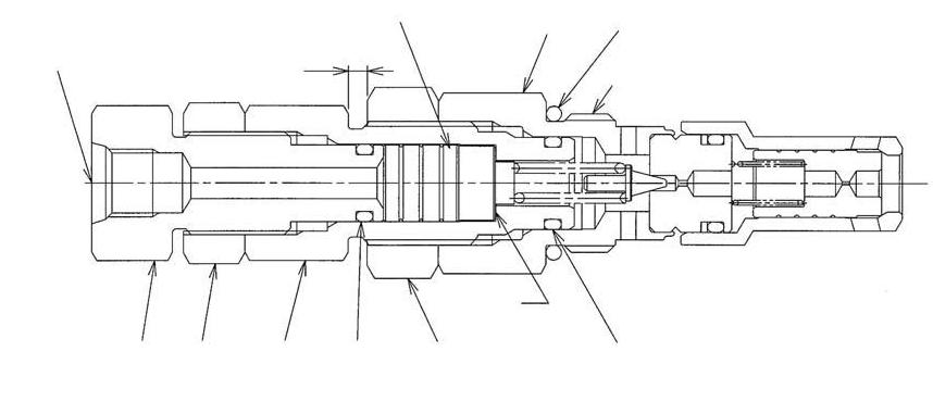
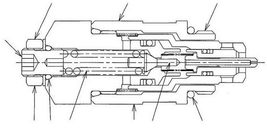
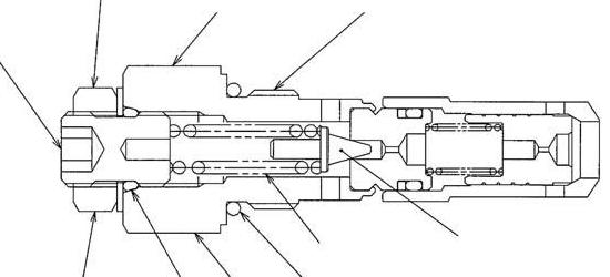
Internal Structure Diagram
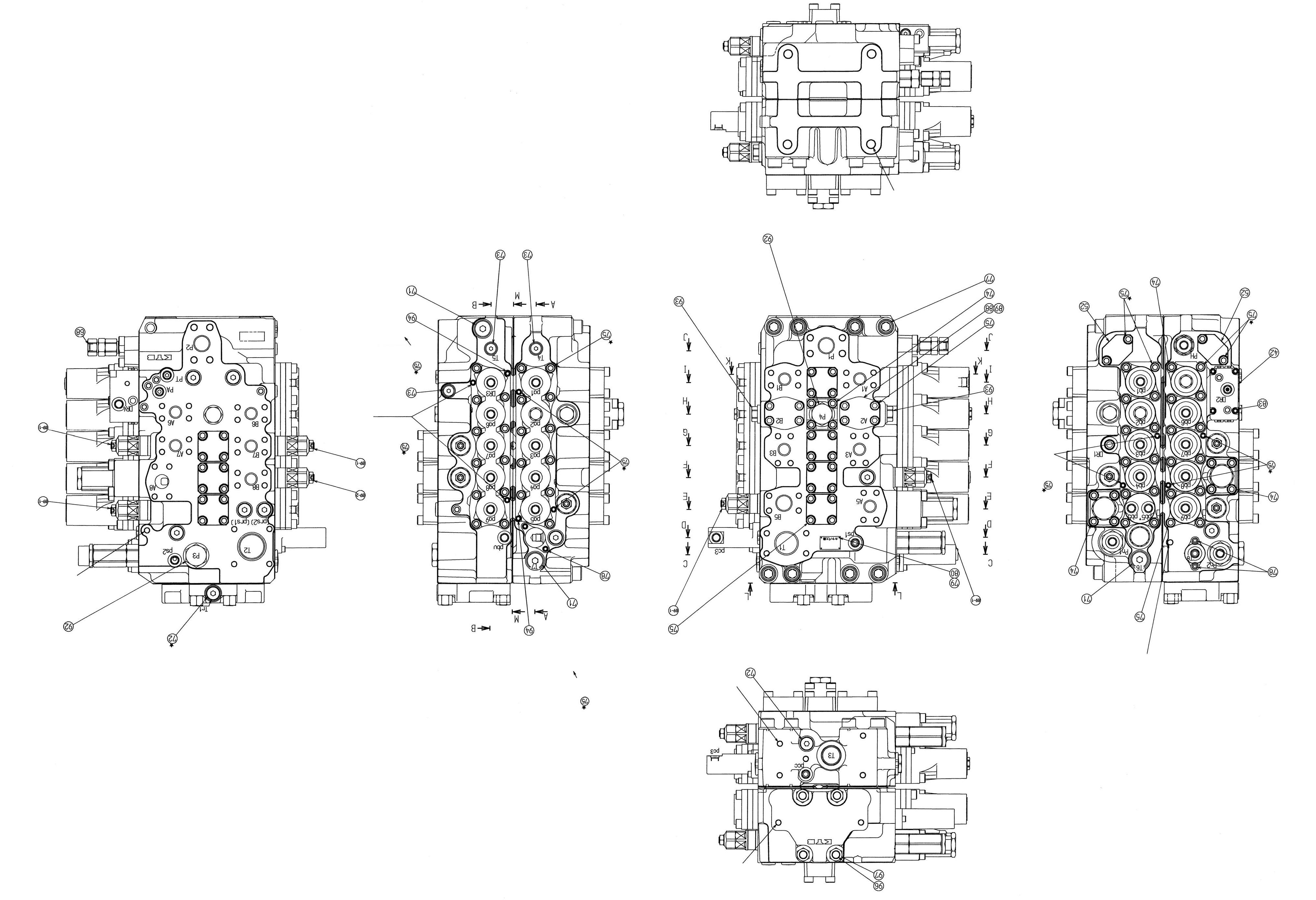
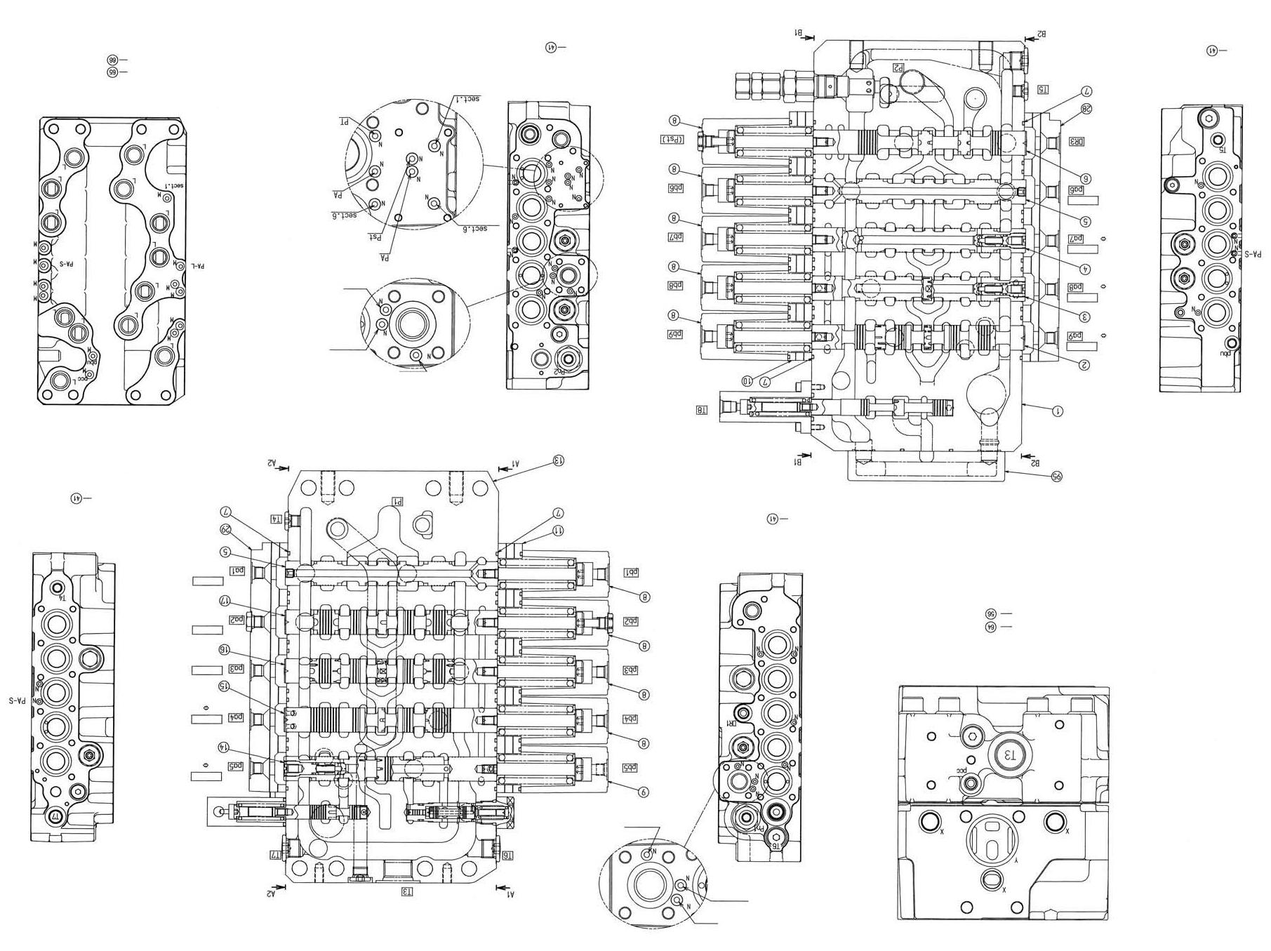
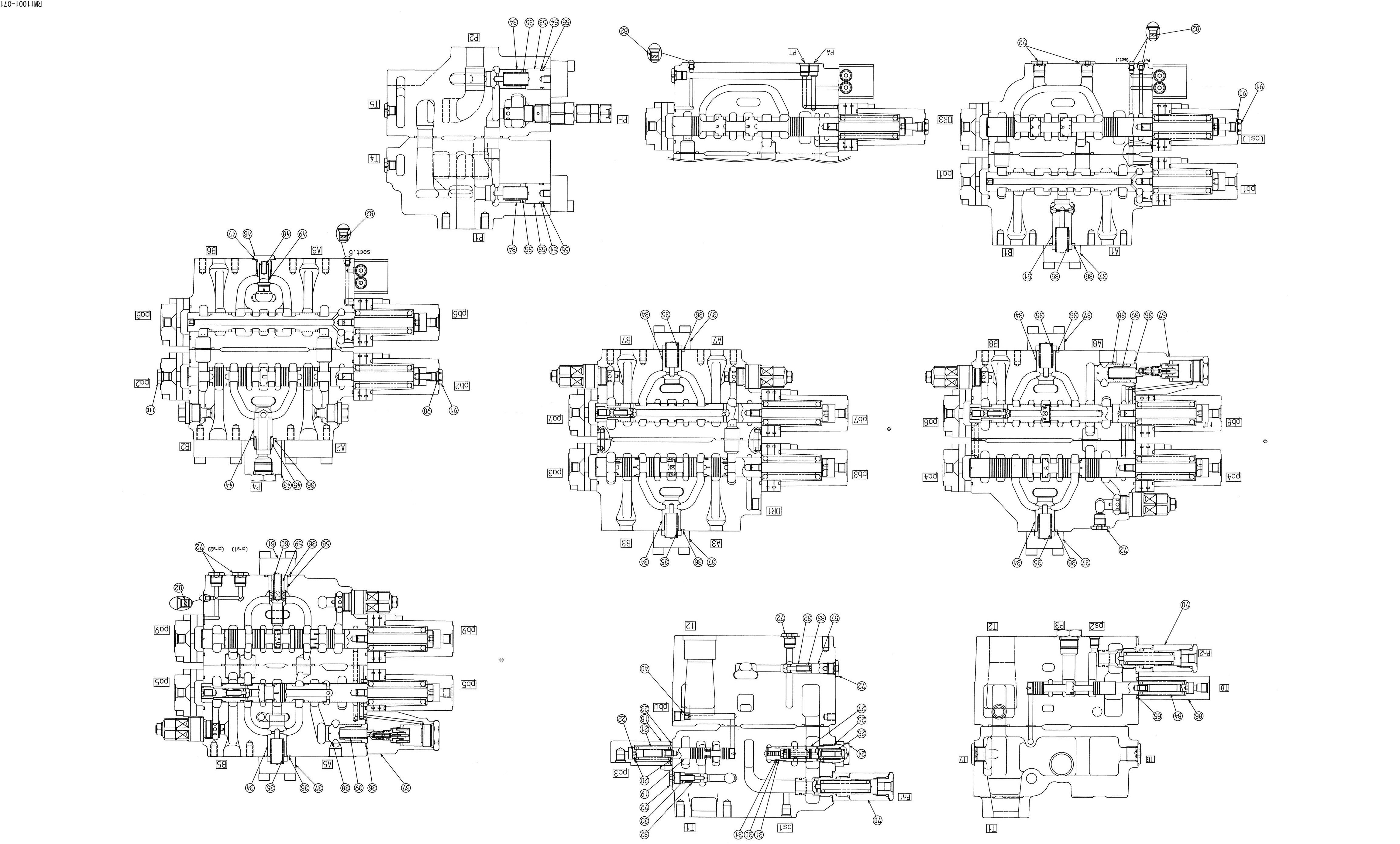
Part list
Code
Part name 1 Valve housing 2 Spool assembly 3 Spool assembly 4 Spool assembly 5 Spool assembly 6 Spool assembly 7 O-ring 8 Cap 9 Cap 10 Plate assembly 11 Plate assembly 13 Valve housing 14 Spool assembly 15 Spool assembly 16 Spool assembly 17 Spool assembly 18 Cap 19 Spool 20 Spring seat 21 Spring 22 Spool end 23 O-ring 24 Plug 25 O-ring 26 Spring 27 Spool assembly 28 Plate assembly 29 Plate assembly 30 O-ring 31 Backup ring 32 Poppet 33 Spring 34 Poppet 35 Spring 36 O-ring 37 Flange 38 Poppet 39 Spring 40 Orifice plug 41 O-ring 42 Body assembly 43 Flange 44 Poppet 45 Spring 46 Plug 47 O-ring Q'ty 1 1 1 1 2 1 20 9 1 1 1 1 1 1 1 1 1 1 2 1 1 1 1 1 1 1 1 1 1 2 2 2 7 8 10 6 2 2 1 27 1 1 1 1 1 1 Code 48 Spring 49 Poppet 51 Poppet 52 Flange 53 Spacer 54 O-ring 55 Backup ring 56 O-ring 57 Spacer 58 Sleeve Part name
59 Poppet 60 Spring 61 Flange 64 O-ring 65 O-ring 66 O-ring 67 Antidrift valve assembly 68 Relief valve kit 69-1 Relief valve kit 69-2 Relief valve kit 70 Relief valve kit 71 Plug assembly 72 Plug assembly 73 Plug assembly 74 Hexagon socket head bolt 75 Hexagon socket head bolt 77 Hexagon socket head bolt 78 Hexagon socket head bolt 79 Nameplate 80 Drive screw 82 Metal plug 83 Hexagon socket head bolt 84 Spool assembly 86 Cap 88 Cap 89 O-ring 90 O-ring 91 Plug 92 Plug assembly 93 Plug assembly 94 Hexagon socket head bolt 95 Outlet housing 96 Tie rod 97 Nut 110 Plug assembly Q'ty 1 1 1 2 2 2 2 1 1 1 1 1 1 3 14 12 2 1 5 1 2 3 10 3 24 74 8 4 1 2 5 4 1 1 2 2 2 2 2 2 2 1 4 4 1
(6)Relief valve 1)Procedures for assembly and disassembly of main relief valve
[1] Disassembly
This part is replaced as an assembly.
When replacing, loosen the plug (1) (32 mm diameter) with a wrench and remove the O-ring (2).
If oil leaks from the nut (4) (36 mm hex diameter), loosen the nut (4) (36 mm hex diameter) and the plug (1) (32 mm hex diameter), and replace the O-ring (3).
If oil leaks from the nut (7) (30 mm hex diameter), loosen the nut (7) (30 mm hex diameter) and the plug (8) (27 mm hex diameter), and replace the O-ring (5). [2] Assembly
Carefully check to make sure there is no debris, paint fragments around the thread sections of the plugs (1) (32 mm hex diameter), (6) (27 mm hex diameter), (8) (27 mm hex diameter) and nuts (4) (36 mm hex diameter), (7) (30 mm hex diameter) and assemble the new O-rings.
Also clean the valve housing relief valve installation section well, install the relief valve, and tighten the plug (1) (32 mm hex diameter).
Tightening torque: 78 - 88 N•m
When the plug has been disassembled, adjust the pressure according to 5) a) Main relief valve.
1 Plug (32 mm hex diameter) 7 Hexagon nut (30 mm hex diameter)
2 O-ring
8 Plug (27 mm hex diameter) 3 O-ring 9 1-1/16-12UN-2A 4 Hexagon nut (36 mm hex diameter) 10 Piston 5 O-ring 11 PF1/4 JIS O-ring type 6 Plug (27 mm hex diameter)
2)Procedures for assembly and disassembly of overload relief valve
[1] Disassembly
This part is replaced as an assembly.
When replacing, loosen the cap (1) (31.75 mm hex diameter) with a wrench and remove the
O-ring (2).
Also, if oil leaks from the adjuster kit section, loosen the adjuster kit and replace the O-ring (4).
[2] Assembly
Check carefully that there is no debris, paint fragments around the thread section of the cap and assemble a new O-ring (2).
Also clean the valve housing relief valve installation section well, install the relief valve, and tighten the cap (1) (31.75 mm hex diameter).
Tightening torque: 78 - 88 N•m
When the adjuster kit has been disassembled, clean around the thread sections well and adjust the pressure according to 5) b) Overload relief valve.
1 Cap 2 O-ring 3 Adjuster kit section 4 O-ring 5 Poppet 6 Spring 7 1-1/16-12UN-2A 8 Cap (31.75 mm hex diameter) 9 Lock nut (17 mm hex diameter) 10 Adjuster (6 mm hex diameter)
Caution Be careful when disassembling the adjuster kit. The spring may make parts fly out and the poppet could be lost.
3)Procedures for assembly and disassembly of low-pressure relief valve
[1] Disassembly
Fasten the assembly with a vise, loosen the plug, and remove the piston (6), spring (4), and poppet (2). Then loosen the plug and take out the O-rings (5) and (8) from each part. [2] Assembly
Check carefully that there is no debris, paint fragments around the thread section of the plug and assemble a new O-ring. Install new O-rings (5) and (8) on the plug and install the plug.
Assemble the poppet (2), spring (4), and piston (6) and screw in and tighten the plug.
Tightening torque: 103 - 113 N•m
Also clean the valve housing relief valve installation section well and tighten the relief valve assembly plug (1) (36 mm hex diameter).
Tightening torque: 103 - 113 N•m
1 Plug 2 Poppet 3 Plug 4 Spring 5 O-ring 6 Piston 7 Plug 8 O-ring 9 PF1/4 10 PF3/4 11 1 3/16-12UN-2A
4)Procedures for assembly and disassembly of add-on main relief valve
[1] Disassembly
This part is replaced as an assembly.
When replacing, loosen the plug (1) (32 mm hex diameter) with a wrench and remove the Oring (2).
Also, if oil leaks from the adjuster kit section, loosen the adjuster kit and replace the O-ring (4).
[2] Assembly
Check carefully that there is no debris, paint fragments around the thread section of the plug and assemble a new O-ring (2).
Also clean the valve housing relief valve installation section well, install the relief valve, and tighten the plug.
Tightening torque: 59 - 69 N•m
When the adjuster kit has been disassembled, clean around the thread sections well and adjust the pressure according to 5) c) Add-on main relief valve.
1 Plug (32 mm hex diameter) 2 O-ring 3 Adjuster kit section 4 O-ring 5 Poppet 6 Spring 7 1-5/16-12UN-2A 8 Plug (24 mm hex diameter) 9 Lock nut (17 mm hex diameter) 10 Adjuster (6 mm hex diameter)
Caution Be careful disassembling the adjuster kit. The spring may make parts fly out and the poppet could be lost.
5)Relief valve adjustment
a)Main relief valve [1] Install an accurate pressure gauge in the entry circuit. [2] Run the pump at its rated rotation rate. [3] Switch the control valve spool and read the pressure gauge at the cylinder stroke end.
[4] High pressure setting (1st stage) (See the diagram on “Relief valve page327”.) 1) Tighten the plug (8) until the piston (10) touches the plug (6) end surface (section marked *). At this time, the plug (8) (27 mm hex diameter) tightening torque must be 19.6 N•m or less. However, when tightening the plug (8), be careful that the plug does not turn too. (The A dimension must be at least 4 mm.) 2) With the plug (6) in the state in [4] 1), tighten and adjust the pressure. (While watching the pressure gauge, tighten in the plug (6) gradually: One turn of the plug raises the pressure 28.4 MPa.) After setting the pressure, lock with the hexagon nut. [5] Low pressure setting (2nd stage) With the high pressure set in [4], loosen the plug (8) and adjust the pressure. (When the plug is loosened, the piston moves to the right in the diagram and the spring load drops: 21.3 MPa pressure drop per one rotation.) After setting the pressure, lock with the hexagon nut (7). [6] Again raise the pressure and check that it reaches the specified pressure. b)Overload relief valve
[1] Switch the control valve spool and read the pressure gauge at the cylinder stroke end. [2] Turn the adjuster clockwise until the required pressure is obtained. [3] Reference number 69, total of 6 locations: The pressure rises 21.2 MPa for one rotation of the adjuster. [4] When the specified pressure is reached, restrain the adjuster so that it does not turn, then tighten the lock nut.
Tightening torque: 27.5 - 31.4 N•m [5] Again raise the pressure and check that it reaches the specified pressure.
Caution This part is neither disassembled nor adjusted. (It is replaced as an assembly.) Therefore, be aware that proper operation is not guaranteed if pressure is adjusted.
Caution Switch the spool for the actuator with the overload relief valve set pressure higher than the main relief valve set pressure.
Caution If the set pressure is higher than the main relief valve, when adjusting as below, the main relief valve operates, so the overload relief valve cannot be adjusted. That is why the relief valve is not disassembled and adjusted but is replaced as an assembly with an assembly that has already been set.
c)Add-on main relief valve [1] Install an accurate pressure gauge in the entry circuit. [2] Run the pump at its rated rotation rate. [3] Switch the control valve spool and read the pressure gauge at the cylinder stroke end.
[4] Turn the adjuster clockwise until the required pressure is obtained. The pressure rises 17.8 MPa for one rotation of the adjuster. [5] When the specified pressure is reached, restrain the adjuster so that it does not turn, then tighten the lock nut. Tightening torque: 27 - 31 N•m [6] Again raise the pressure and check that it reaches the specified pressure. (7)Installation [1] Be careful that the line does not apply excessive force to the valve. [2] Tighten all the bolts the same. [3] Be careful. Welding close to a valve can damage its seal due to excess heat and sputter. [4] In order to keep out debris, do not remove the cap for a port until it is time to work on the line. (8)Operation [1] Check that the hydraulic circuits and hydraulic oil are clean, then gradually raise the pressure (inch the operating machine in low idle) and check that no oil leaks to the outside. [2] For the oil, use hydraulic oil with an aniline point of 82 - 113 ℃ . [3] Do not raise the relief valve above the specified set pressure. [4] Set a difference of at least 2.0 MPa between the set pressure for the main relief valve and for the overload relief valve. [5] Warm up the machine adequately before starting the actual work. Pay attention to the following points in order to avoid sticking due to spool heat shock particularly when starting up with the hydraulic oil temperature or valve temperature low. •Do not operate the main relief valve and overload relief valve right too suddenly after each other. Raise the temperature of each section uniformly and operate in such a way that the hydraulic oil circulates within each actuator. •Fine operations and compound operations generate heat locally due to throttling of individual sections, so do not suddenly perform these operations with the machine still at low temperature.
Caution Switch the spool for the actuator with the overload relief valve set pressure higher than the main relief valve set pressure.
(9)Troubles and countermeasures
Control valves overall
Trouble content
The spool does not move through its stroke.
The load cannot be held.
When the spool is switched from the neutral to the raise position, the load falls. Conceivable cause Countermeasure
1. The oil temperature is abnormally high. Eliminate the section that is providing resistance to the oil flow in the line.
2. Dirty hydraulic oil
Replace the hydraulic oil and at the same time, clean the circuits. 3. Line port joint tightened too much Check the torque. 4. The valve housing was warped during installation. Loosen the installation bolts and check. 5. The pressure is too high. Attach a pressure gauge to the pump and the cylinder port and check the pressure.
6. The spool is bent. Replace the spool as an assembly.
7. Return spring damage
Replace the damaged part. 8. The spring or cap is out of place. Loosen the cap, center it, then tighten it. 9. The temperature distribution within the valve is not uniform. Warm up the circuits as a whole. 10.Debris is clogging inside the valve. Remove (flush out) the debris. 11.Pilot pressure insufficient Inspect for the pilot valve and pilot relief pressure. 1. Oil leak from cylinder Check the cylinder seal section. 2. Oil from the spool is bypassing. Check for spool damage. 3. Oil leak from overload relief valve Clean the valve housing seat section and relief valve seat section. 4. Oil leak from antidrift valve Disassemble the antidrift valve and clean the seat section for each part. If a seat section is damaged, replace the poppet or lap the poppet and seat section. If the antidrift valve spool is abnormal, since the spool and the sleeve are mating parts, replace them both at the same time.
1. There is debris jammed in the load check valve. Disassemble and clean the check valve.
2. The check valve poppet or seat section is damaged. Replace the poppet or lap the poppet and seat section.
Relief valve
Trouble content
Pressure does not rise at all.
The relief pressure is unstable.
The relief pressure is wrong.
Oil leak Conceivable cause
1. Either the main poppet, sleeve, or pilot poppet is stuck open or there is debris jammed in the valve seat section. Countermeasure
Replace the relief valve.
1. The pilot poppet seat section is damaged. 2. The piston or main poppet is stuck. 1. Seat section worn by debris 2. The lock nut and adjuster are loose. Set the pressure again, then tighten the lock nut to the specified torque. 1. Relief valve seat section damage Replace the relief valve. 2.Each part is stuck due to debris. 3. An O-ring is worn. Replace the adjuster or installation section Oring.
Hydraulic system overall
Trouble content Conceivable cause Countermeasure
The hydraulic system is not working properly or is not working at all. 1. Pump trouble Check the pressure or replace the pump.
2. Relief valve trouble
Replace the relief valve. 3. Cylinder trouble Repair or replace. 4. Pump load pressure is high. Check the circuit pressure. 5.There is a crack in the valve. Replace the valve as an assembly. 6. The spool does not move through its full stroke. Check the spool movement. 7. The tank oil level is too low. Fill the hydraulic oil. 8. The filter in the circuit is clogged. Clean or replace the filter. 9. The circuit line is throttled. Check the line.
