2 minute read
Removal and Installation of Starter Motor

from Sumitomo SH250-5 SH250-5LR Hydraulic Excavator Service Repair Manual WLSM2105-00W - PDF DOWNLOAD

[9] Removal of O-ring, knock pin and spring
Remove the O-rings (1-22) and (1-23), knock pins (1-19), and springs (1-18).
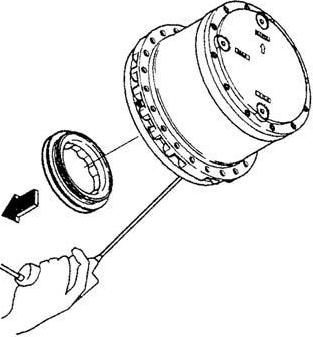
[10]Removal of brake piston
Attach a pressured air nozzle to the flange (1-1) oil path for the parking brake, and inject compressed air to the parking brake cylinder chamber to raise the brake piston (1-15) and remove it.
After removing the brake piston, remove the disk plates (1-13) and friction plates (1-14), and remove the O-rings (1-16) and (1-17) from the brake piston.
Cautions:
When removing the brake piston, observe the following precautions. a.When injecting compressed air from the flange oil path for the parking brake, do not let any compressed air leak out. b.When injecting compressed air from the flange oil path for the parking brake, the brake piston may fly off if the pressure of the compressed air is high, and this may cause injury. For this reason, set the air pressure at 0.29 MPa or below, and hold down the brake piston while performing work so that it does not fly off.

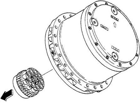
[11]Removal of cylinder block assembly
Remove the cylinder block assembly (1-4) from the flange (1-1).
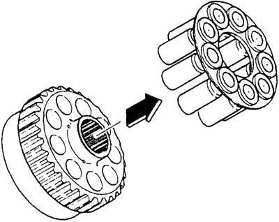
Cautions: When removing the cylinder block assembly, observe the following precautions. a.Grasp the cylinder block assembly with both hands and lightly rotate it left and right to slowly remove it. b.Be careful not to scratch the surface of the cylinder block (1-4-1) that slides against the valve plate (1-21). If this surface is scratched, the machine will no longer display prescribed capabilities. c.Be careful not to scratch the piston assembly (1-4-2) shoe sliding surfaces. If this surface is scratched, the machine will no longer display prescribed capabilities. [12]Disassembly of cylinder block assembly 1) Mark the piston assemblies (1-4-2) and cylinder block (1-4-1) with permanent ink so that parts can be reassembled in the exact same configuration, and remove the piston assemblies and retainer plate (1-4-3) from the cylinder block.
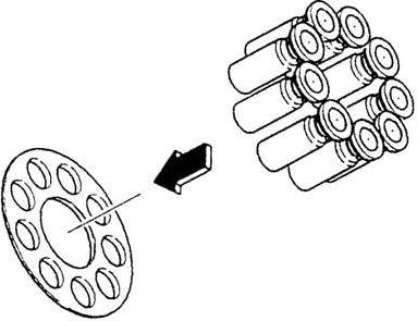
2) Mark the piston assemblies (1-4-2) and retainer plate (1-4-3) with permanent ink so that parts can be reassembled in the exact same configuration, and remove the piston assemblies from the retainer plate.