13 minute read
SH240-5 Assembly and Disassembly of Swing Reduction Gear

from Sumitomo SH250-5 SH250-5LR Hydraulic Excavator Service Repair Manual WLSM2105-00W - PDF DOWNLOAD

Caution 1. Read and understand the contents of this Maintenance Manual before performing disassembly, reassembly, inspection, repair, or other such work of this product. 2. Handle this product according to the separate "Usage Cautions". 3. When removing this product from the equipment it is mounted on, stop that equipment system and wait for the surface temperature of this product to fall to about 40C or below before removing it. Working on this product while it is still hot can cause burns. Additionally, always bleed out the pressure before removing any line from this product. Removing a pressurized line can result in oil spraying out and causing burns and oil leaking. 4. Use the specialty tools and measurement instruments for disassembly, reassembly, inspection, and repair, etc. of this product. Using an inappropriate tool may result in injury or product damage. 5. Be careful of parts falling when performing disassembly, reassembly, inspection or repair, etc. of this product. This may result in injury or parts damage. 6. Do not directly touch with bare hands the machined edges or threaded sections of parts during disassembly, reassembly, inspection, or repair etc. of this product. This may result in injury. 7. Check performance after reassembly. Do not resume use unless performance is fully recovered. Using this product at a sub-par performance level may result in product damage. 8. The cautions (mark !) listed in this Maintenance Manual do not cover all possible dangers.
Always think of safety first during disassembly, inspection, reassembly, repair, or other such work.
1.Disassembly [1] Put the nylon sling around the swing motor section and lift it with a crane.
[2] Place the swing unit on the bracket (8098413), and secure it with the 2 bolts (M24). Secure the bracket to the work platform so that reactive force is absorbed. : 36 mm
[3] Remove the drain plug (25), and then drain oil. : 22 mm
[4] Remove the hose (24) from the housing (31). : 22 mm
[5] Place reference marks on the matching sections of the motor (2) and ring gear (22) and the ring gear and housing (31). Loosen and remove the hexagon socket head bolts (1) and lift the motor with a crane to remove it. : 10 mm
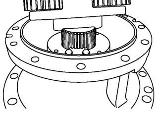
[6] Remove the 1st stage sun gear (4) and 1st stage carrier (21) assembly from the ring gear (22). : 8 mm
[7] Loosen and remove the hexagon socket head bolts (32) and install eyebolts (M12, 1.75 mm pitch) on the motor installation screw section of the ring gear (22). Remove the ring gear from the housing (31) lifted by the crane. : 14 mm
[8] Remove the 2nd stage sun gear (20) and 2nd stage carrier (19) assembly.
Caution Swing unit weight: about 301 kg
*1 Swing unit *2 Bracket (8098413)
Caution Motor weight: 71 kg
Tip: Inserting a flathead screwdriver in the gap between the motor and ring gear will make the motor rise up and make it easier to remove.
Caution Ring gear weight: 27 kg
Tip: ThreeBond has been applied to the matching surfaces of the housing and ring gear. Placing a flathead screwdriver in the notch section of the matching section outer circumference raises the ring gear and makes it easier to remove.
Caution 2nd stage carrier assembly weight: 32 kg
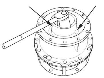
[9] Remove the bolts (17), and then remove the lock plate (16). [10]Use the nut removal and installation jig (8083297) (*1) to remove the nut (15) from the shaft (26).
[11]Install eyebolts (M18, 2.5 mm pitch) in the bolt holes on the housing (31).
Remove the 2 bolts (M24) securing the housing and bracket.
Lift the housing assembly with a crane and remove the bracket.
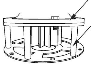
[12]Set the housing assembly on top of the blocks (*1) set on the press platform.
Caution Housing assembly weight: 148 kg

[13]Place an upper lid (*1) on the housing (31) before removing the shaft (26) with the press (*2). At this time, the roller bearing (30) inner race and sleeve (29) will become attached to the shaft.
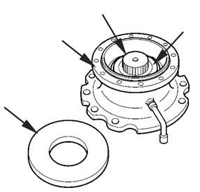
[14]Remove the roller bearing (30) inner race from the housing (31). [15]Set a jig on the shaft assembly (26).
Bearing removal jig
Caution When pressing on the shaft with the press, make sure to produce an upper lid (outer diameter 369 mm, inner diameter 90 mm, thickness 25 - 30 mm) and do pressing with the upper lid in place. There is a possibility of the housing and roller bearing breaking and fragments flying off, which may cause injury. Also, the upper limit of the press is 30 t. When heating the roller bearing, thoroughly degrease the inside of the housing before heating. If heating is done without degreasing, there is the danger of fires occurring.
Tip: Use the following items for the roller bearing removal jig. Shafts (bolts are also useable): length 220 mm, diameter 19 mm x 8 (*1) (All should be the same length and have no wear deformation on either end) Raw materials: S35C Hose clamp: (standard diameter of 8-1/2 inches, tightening range of 185 - 215 mm) x 2 (*2) Guide: height 160 mm, outer diameter 250 mm, inner diameter 230 mm (*3)

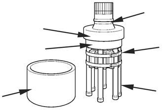
[16]Set the shaft (26) with the jig attached in the press (*1) to remove the roller bearing (30). [17]Remove the sleeve (29) from the shaft (26), and remove the O-ring (27) from the sleeve.
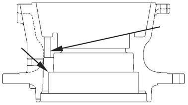
[18]Insert the round rod into the internal oil path (*2) of the housing (31), and strike the outer race (*1) of the roller bearing (23) to remove it.
[19]Bind the body of the housing (31) with the nylon sling, lift it with a crane, and turn the housing around. Insert a screwdriver into the notch section of the oil seal (28) installation section of the housing and remove the oil seal.
[20]Use a striking rod and hammer to strike the back surface of the roller bearing (30) outer race, and remove the outer race from the housing (31). [21]Use a round rod and hammer to remove the spring pins (6) from the 1st stage carrier (21). [22]Remove the 3 pins (5), 3 1st stage planetary gears (9), 3 thrust plates (7), and 3 needle bearings (8) from the 1st stage carrier (21). [23]Remove the thrust plate (18) from the 1st stage carrier (21). [24]Use a round rod and hammer to remove the spring pins (11) from the 2nd stage carrier (19).
Caution When pressing the shaft with the press, be sure to do this within the guide.
Caution Housing (31) weight: 104 kg
Tip: ThreeBond has been applied to the outer circumference of the oil seal. Accordingly, the oil seal cannot be reused.
[25]Remove the 3 pins (10), 3 2nd stage planetary gears (14), 3 thrust plates (12), and 6 needle bearings (13) from the 2nd stage carrier (19). [26]Remove the thrust plate (18) from the 2nd stage carrier (19).
This completes the disassembly. Thoroughly inspect each section for abnormalities.
2.Assembly [1] Preparation before operation Execute the following preparations before reassembly. 1) Check each part for scratches from use or from disassembly. If there are any scratches, remove them with a whetstone or sandpaper of the necessary grain, clean with cleaning oil, then dry off with an air blower. 2) Replace seal parts with new ones. 3) When assembling sliding sections, apply clean hydraulic oil before assembling. [2] Install 1 needle bearing (8) into each of the 3 1st stage planetary gears (9). [3] Install the thrust plate (18) into the 1st stage carrier (21) with the side of the thrust plate with the oil groove facing upwards. [4] Install the 3 1st stage planetary gears (9) and 3 thrust plates (7) into the 1st stage carrier (21). [5] Align the 3 pins (5) with the spring pin holes of the 1st stage carrier (21) and strike the pins with a hammer to install them.
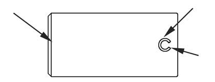
[6] Arrange the spring pins (6) so that the slit section (*1) faces the end surface of the pins, and drive the spring pins into the 1st stage carrier (21) and pins (5) with a hammer.
[7] Assemble the 2nd stage carrier in the same sequence as shown in Step [2] - [6]. Assemble the 3 2nd stage planetary gears (14), 6 needle bearings (13), 3 thrust plates (12), 1 thrust plate (18), 3 pins (10), and 3 spring pins (11). [8] Install the O-ring (27) into the sleeve (29).
Important: Be careful with the direction of the spring pins.
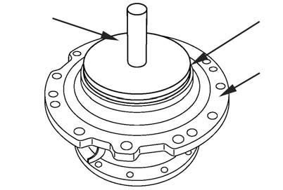
[9] Install the sleeve (29) and inner race of the roller bearing (30) into the shaft (26). Use the bearing press-fit jig (ST A) (ST B) to press fit the sleeve and inner race with the press (*1).

Tip: The press-fit amount of the bearing inner race is preserved by using the press-fit jig.
[10]Bind the body of the housing (31) with the nylon sling. Lift the housing with a crane, and set it down with the sleeve (29) installation side facing up.
Caution Housing weight: 104 kg
[11]Use a striking rod and hammer to evenly strike the roller bearing (30) outer race and install it in the housing. Listen for the sound of the outer race striking the bottom to check that it is fully in. [12]Apply ThreeBond #1205 to the outer circumference of the oil seal (28). Place the oil seal on the housing (31) so that it is level, and press the oil seal in a small amount by hand. Place the seal installation jig (8026527) (*1) on top of the oil seal and strike it straight with the hammer.
[13]Apply grease to the inner circumference of the oil seal (28). Additionally, also apply grease to the outer circumference surface of the sleeve (29) attached to the shaft (26).
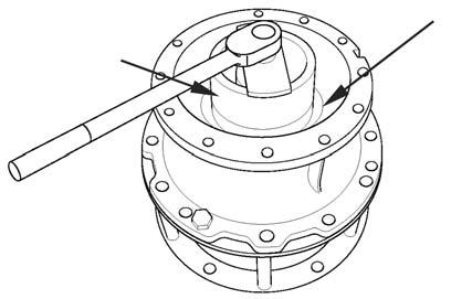
[14]Install eyebolts (M18, 2.5 mm pitch) in the bolt holes on the housing (31). Lift the housing and slowly lower it over the shaft (26) to fit it on the shaft. At this time, carefully perform centering during assembly so that the oil seal (28) lip does not get turned up. [15]Use a striking rod and hammer to evenly strike the roller bearing (23) outer race and install it in the housing (31). Listen for the sound of the outer race striking the bottom to check that it is fully in. [16]Use a striking rod and hammer to hammer the roller bearing (23) inner race into the shaft (26).
Hammer in the inner race so that the top surface of the inner race is 2 threads down from the threaded section for the shaft nut (15). [17]Tighten the nut (15) onto the shaft (26) to the maximum degree it can be tighten by hand. Tip: This prevents the shaft from falling when the housing is lifted.
[18]Attach eyebolts (M18, 2.5 mm pitch) into the bolt holes of the housing (31), and lift the housing with a crane and set it on the press.
Caution Housing + shaft + bearing weight: 148 kg
[19]Remove the nut (15) from the shaft (26). [20]Place the inner race press-fit jig (ST C) on the roller bearing (23) inner race and press-fit the inner race with the press. Tip: The specified amount to which the inner race is pressed in can be preserved by using the press-fit jig.

[21]Lift the housing (31) assembly with a crane, place it on the bracket (8098413) (*2), and install it using the 2 bolts (M24). At this time, the stopper on the bottom section of the bracket (*1) should be arranged so that it can be inserted in between the pinion gear teeth. Additionally, secure the bracket to the work platform so that reactive force is absorbed. : 36 mm
[22]Apply a small amount of grease to the threaded section of the nut (15) and install it on the shaft (26). At this time, place the stepped end surface of the nut on the roller bearing (23) side. Use the nut tightening jig (8083297) (*1) to tighten it to the specified torque. : 735 N•m
[23]Install the lock plate (16) on the nut (15) using the bolts (17). When the lock plate spline does not fit with the shaft (26) spline, retorque the lock plate in the nut tightening direction to align the splines. : 17 mm : 50 N•m

Important: Be careful with the attachment direction of the bearing nut.
Tip: Be sure to apply grease to preserve the correct tightening torque.
[24]Attach the 2nd stage carrier (19) assembly to the shaft (26) spline.
[25]Install the 2nd stage sun gear (20) into the 2nd stage carrier (19) assembly. [26]Apply ThreeBond #1215 to the ring gear (22) installation surface of the housing (31). At this time, thoroughly remove old adhesive. [27]Attach eyebolts (M12, 1.75 mm pitch) to the motor installation threaded sections of the ring gear (22), lift with a crane, and align the reference marks made during disassembly to install the ring gear to the housing (31).
Tighten the 12 hexagon socket head bolts (32). : 14 mm : 300 N•m
[28]Align the 1st stage carrier (21) assembly with the spline of the 2nd stage sun gear (20) to install the assembly.
[29]Attach the 1st stage sun gear (4) to the 1st stage carrier (21) assembly with the stepped end surface facing downwards. [30]Wrap the hose (24) threaded section with seal tape and install it on the housing (31). : 22 mm [31]Install the drain plug (25) on the hose. : 22 mm : 50 N•m [32]Fill with gear oil (9.7 L). [33]Apply liquid packing (ThreeBond #1215) to the ring gear (22) motor installation surface.
Caution 2nd stage carrier weight: 32 kg
Important: Be careful to install the carrier in the correct direction.
Caution Ring gear weight: 27 kg
Important: Be careful with the attachment direction of the sun gear.
[34]Lift the motor with a crane, align the reference marks made during disassembly, and install it onto the ring gear (22) with the 12 hexagon socket head bolts (1). : 10 mm : 90 N•m
This completes the assembly.
Caution Motor weight: 71 kg
Swing Reduction Gear Breakdown Diagram

Swing Reduction Gear Structure Diagram
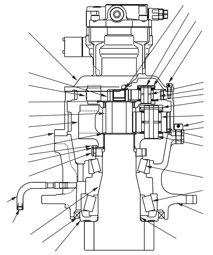
1 Hexagon socket head bolt (12) 12 Thrust plate (3) 2 Swing motor 13 Needle bearing (6) 23 Roller bearing 24 Hose
3 Retaining ring 4 1st stage sun gear 5 Pin (3) 6 Spring pin (3) 7 Thrust plate (3) 14 2nd stage planetary gear (3) 25 Drain plug 15 Nut 26 Shaft
16 Lock plate 17 Bolt (2) 18 Thrust plate (2) 27 O-ring 28 Oil seal 29 Sleeve
8 Needle bearing (3)
19 2nd stage carrier 9 1st stage planetary gear (3) 20 2nd stage sun gear 10 Pin (3) 11 Spring pin (3) 21 1st stage carrier 22 Ring gear 30 Roller bearing 31 Housing 32 Hexagon socket head bolt (12)
