19 minute read
SH210-5 Assembly and Disassembly of Swing Motor

from Sumitomo SH250-5 SH250-5LR Hydraulic Excavator Service Repair Manual WLSM2105-00W - PDF DOWNLOAD

Caution 1. Read and understand the contents of this Maintenance Manual before performing disassembly, reassembly, inspection, repair, or other such work of this product. 2. Handle this product according to the separate "Usage Cautions". 3. When removing this product from the equipment it is mounted on, stop that equipment system and wait for the surface temperature of this product to fall to about 40 ℃ or below before removing it. Working on this product while it is still hot can cause burns. Additionally, always bleed out the pressure before removing any line from this product. Removing a pressurized line can result in oil spraying out and causing burns and oil leaking. 4. Use the specialty tools and measurement instruments for disassembly, reassembly, inspection, and repair, etc. of this product. Using an inappropriate tool may result in injury or product damage. 5. Be careful of parts falling when performing disassembly, reassembly, inspection or repair, etc. of this product. This may result in injury or parts damage. 6. Do not directly touch with bare hands the machined edges or threaded sections of parts during disassembly, reassembly, inspection, or repair etc. of this product. This may result in injury. 7. Check performance after reassembly. Do not resume use unless performance is fully recovered. Using this product at a sub-par performance level may result in product damage. 8. The cautions (mark !) listed in this Maintenance Manual do not cover all possible dangers.
Always think of safety first during disassembly, inspection, reassembly, repair, or other such work.
1.Causes of Trouble and Solutions
This list consists of actions to be taken when an abnormality is sensed or there are problems with functions during use of the hydraulic motor. Additionally, details concerning disassembly inspection and reassembly are listed after this, but sufficient caution should be exercised in handling during these actions so as to prevent scratching of sliding parts of the motor.
Table 1
Symptom Cause External inspection
Internal motor damage
No rotation Internal motor damage
Setting problem with relief valve within the circuit Measure the amount of drained oil.
Open the motor inlet and outlet ports and apply 3.2 - 4.9 MPa of pilot pressure to the brake release port, and attempt to turn the output shaft using about 30 - 40 N•m of torque.
Measure the load pressure with the pressure gauge. Solution
It is very likely that sliding section is damaged when the oil fed to the motor is mostly being drained, so disassembly inspection is necessary.
It is very likely that there is internal damage if the output shaft does not turn smoothly at the torque listed to the left, so disassembly inspection is necessary.
Reset to the correct set pressure.
Severe slipping
Abnormal noise due to insufficient torque Wear or damage on sliding section or high-pressure seal section of the motor
High oil temperature and high internal motor leaking
Wear or seizing on motor sliding section
Setting problem with relief valve within the circuit
Internal motor damage
Large amount of air in oil
Looseness in tightening section Measure the amount of drained oil. The leaking amount is high if the amount of drained oil is 2.5 L/min or more, so disassembly inspection is necessary.
Measure the oil temperature. Lower the oil temperature.
Open the motor inlet and outlet ports and apply 3.2 - 4.9 MPa of pilot pressure to the brake release port, and attempt to turn the output shaft using about 30 - 40 N・ m of torque.
Measure the load pressure with the pressure gauge.
Check for metallic foreign matter in oil drained from the motor and within the return filter.
Inspect oil within the tank and motor case.
Check for looseness in line fitting, fitting installation bolt, motor installation bolt and each bolt on the motor. It is very likely that there is internal damage if the output shaft does not turn smoothly at the torque listed to the left, so disassembly inspection is necessary.
Reset to the correct set pressure.
It is very likely that there is internal motor damage if metallic foreign matter is discovered, so disassembly inspection is necessary. Thoroughly perform air bleeding.
Tighten the bolt(s) to the appropriate torque. Correction
See Table 2
Replace damaged part(s) or motor assembly.
See Table 2
Inspect the parts and bearings in a - e of Table 2, and perform replacement if there are any abnormalities.
Repair or replace damaged part(s). Replace motor assembly.
Symptom Cause External inspection Solution Correction
Abnormal generation of heat
Oil leaking from matching surface Seizing in motor sliding or rotating section
Scratched O-ring Check for metallic foreign matter in oil drained from the motor and within the return filter. Also, apply 3.2 - 4.9 MPa of pilot pressure to the brake release port and attempt to turn the output shaft using about 30 - 40 N•m of torque. It is very likely that there is internal motor damage if metallic foreign matter is discovered or the output shaft does not turn smoothly at the torque listed to the left, so disassembly inspection is necessary.
Scratched seal surface
Looseness in bolt. Inspect looseness in bolt. Tighten the bolt(s) to the appropriate torque. Repair or replace damaged part(s). Replace motor assembly.
Replace Oring(s). Repair seal surface(s) or replace seal(s).
Oil leaking from oil seal Scratching or wear on the oil seal lip section Scratching or wear on the seal section of the shaft
Abnormal internal case pressure Check the internal case pressure and amount of drained oil. Replace oil seal(s).
Lower the internal case pressure to 0.3 MPa or below. If the amount of drained oil is high, disassembly inspection is necessary. Repair part(s) or replace the motor assembly.
Replace oil seal(s). Repair or replace damaged part(s). Replace motor assembly.
Table 2
No. Inspection part Correction a Wear on balance plate (21) sliding section Repair or replace part. b Damage to cam plate (5) sliding section Repair part or replace motor. c Damage to piston assembly (7) sliding section(s) Repair part(s) or replace motor. d Wear on piston outer diameters of piston assembly (7) Repair part(s) or replace motor e Wear on cylinder (24) piston hole(s) Replace motor f Damage to teflon ring(s) (19) Replace part(s)
2.Maintenance Standard Table
Table 1
Part name Inspection and measurement location Reference value (permissible limit value) Measurement device Repair, solution procedure
Piston assemblies (7) Shoe sliding surface roughness 0.8 S Surface roughness gauge
Repair with sandpaper lapping. Shoe sliding surface groove depth(s) 0.4 mm or greater Micrometer caliper Replace it (them) with new part(s). Piston and shoe spherical coupling section backlash 0.4 mm or less Dial gauge Replace it (them) with new part(s).
Piston bore(s) There is almost no wear. If there are any scratching or seizing, replace it (them) with new part(s).
Cam plate (5) Surface roughness 0.8 S Surface roughness gauge Lap
Cylinder (24) End surface roughness 0.4 S Surface roughness gauge Lap
Piston holes There is almost no wear. If there are any scratching or seizing, replace the motor.
Balance plate (21) Surface roughness 0.8 S Surface roughness gauge Lap
Piston assemblies (7) Cylinder (24) Gaps between piston bore and cylinder hole 0.04 mm or less Micrometer caliper Air micrometer caliper Replace motor.
Table 2
Part name Inspection and maintenance standards Tapered roller bearing (3) Needle bearing (22) Auto aligning roller bearing (65) Auto aligning roller bearing (71) Even with normal use, bearings need to be replaced with new parts every 3000 hr. of use. Also, make sure to replace them with new parts even within the 3000 hr. limit during reassembly after disassembly. Oil seals (2) (70) If there is scratching on lip(s), replace it (them) with new part(s). Also, even with normal use without any leaks, replace them with new parts every 3000 hr. of use. Also, make sure to replace the O-rings with new ones even within the 3000 hr. limit during reassembly after disassembly.
O-rings(10) (12) (16) (30) (31) (36) (43) (91) (93)
If there is any scratching on O-ring(s), replace it (them) with new part(s). Also, even with normal use without any leaking, replace the O-rings with new ones every 3000 hr. of use. Also, make sure to replace the O-rings with new ones even within the 3000 hr. limit during reassembly after disassembly. Backup rings (29) (41) When reassembling after disassembly, always replace them with new parts.
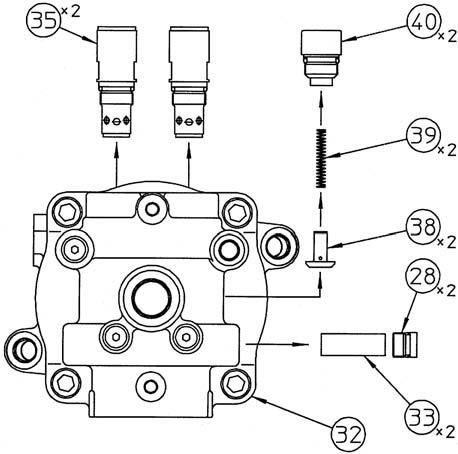
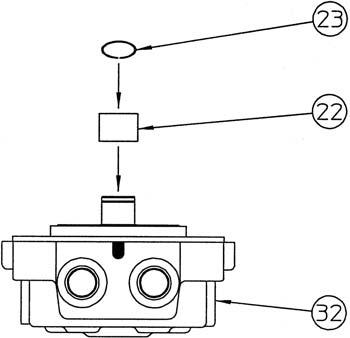
3.Disassembly [1] Removal of relief assembly, etc. Remove the relief valve assemblies (35) (14 mm hex socket diameter), caps (40) (14 mm hex socket diameter), springs (39), checks (38), caps (28) (10 mm hex socket diameter), and plugs (33) from the cover (32). •When reassembling the disassembled relief assemblies, caps, springs, checks, and plugs, make sure to install them in their original locations.
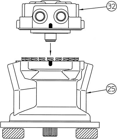
[2] Making a reference mark on the motor matching surface
It is useful for reassembly to make a reference mark (*1) with paint etc. on the matching surface of the cover (32) and housing (25).

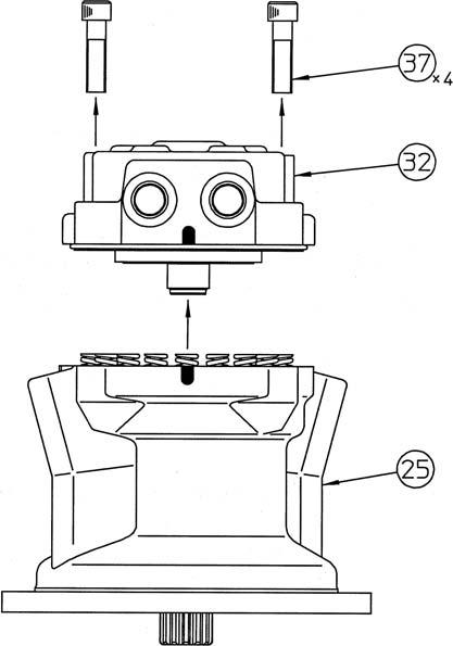
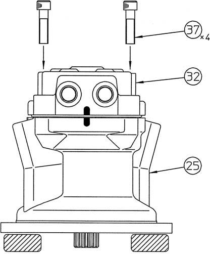
[3] Loosening the tightening bolts
Loosen the hexagon socket head bolts (37) (14 mm hex socket diameter), place the motor with the output shaft facing down, and lift up and remove the cover (32).
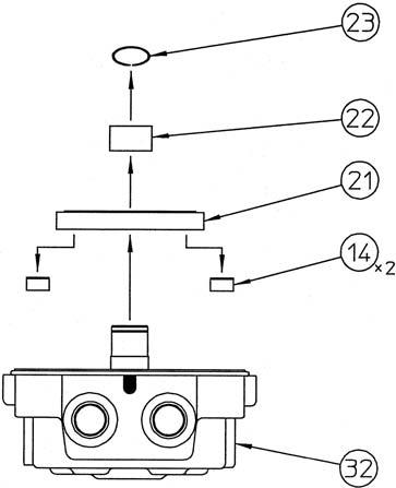
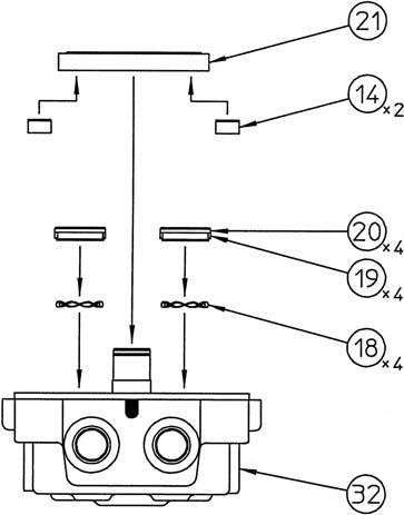
[4] Removal of inner race
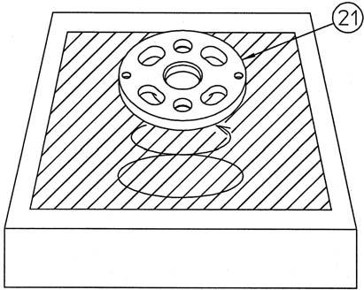
Remove the snap ring (23) with the mark-off pin, and remove the needle bearing (22) inner race and balance plate (21).
At this time, the inner race of the needle bearing is press fit into the male shaft of the cover (32), so place the gear puller in the archshaped groove sections of the balance plate and on the male shaft of the cover to remove the inner race.
Next, take out the pistons (14) from the balance plate. •Be careful not to scratch the sliding surface of the balance plate or apply a great deal of force and cause deformation. •The attachment direction of the balance plate in relation to the cover is set, so place a mark on the balance plate and cover to confirm the attachment direction during reassembly.
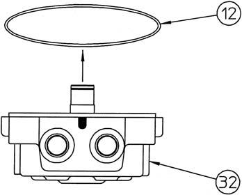
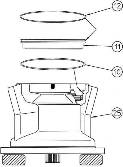
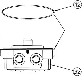
[5] Removal of O-ring
Remove the O-ring (12) from the cover (32).
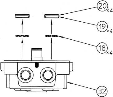
[6] Removal of bushing
Remove the bushings (20) with the teflon rings (19) attached and the Scrowave springs (18) from the cover (32).
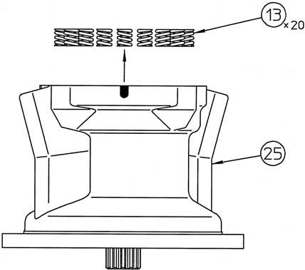
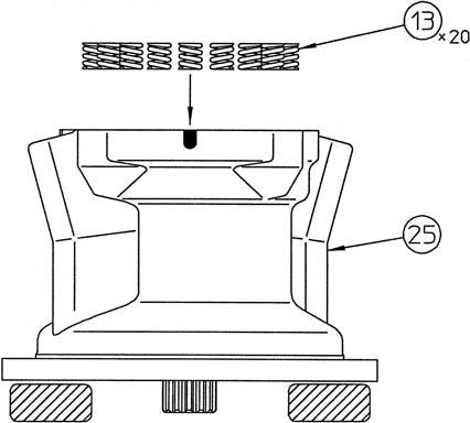
[7] Removal of spring
Take out the springs (13) from the brake piston (11). •Make sure the spring positions for installation on the piston can be determined.
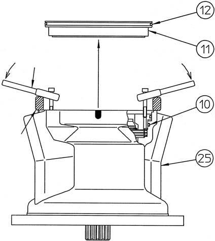
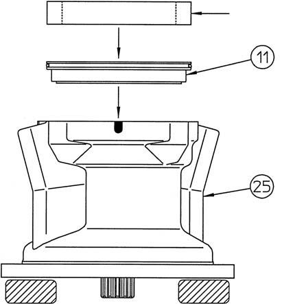
[8] Removal of brake piston
When taking the piston (11) out from the housing (25), sliding resistance occurs due to the force-fitting effect of O-rings (10) and (12). The piston is difficult to remove, so use a monkey wrench (*1) with the tap holes (M6) on the piston as shown in the diagram to remove the piston.
Next, remove O-ring (10) from the housing and
O-ring (12) from the piston. •Place the metal blocks (*2) outside the housing inner diameter.
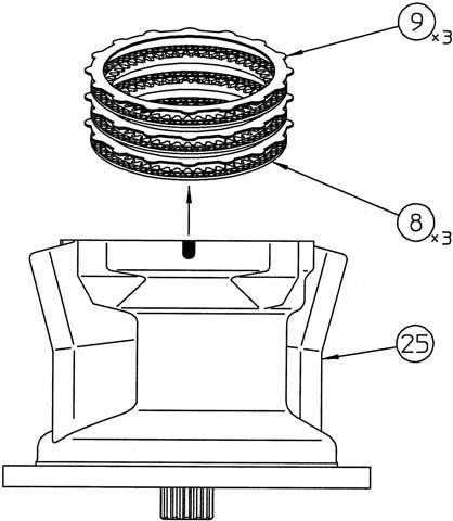
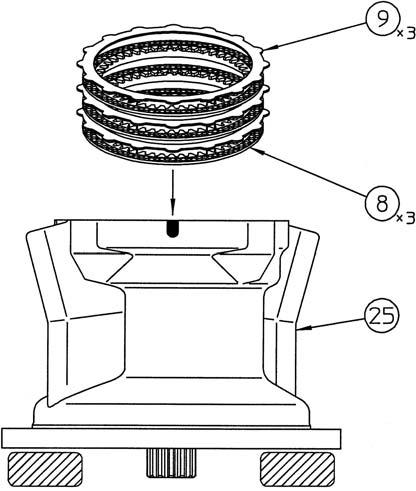
[9] Removal of friction plate and partner plate
Remove the friction plates (8) and partner plates (9).
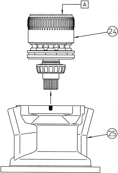
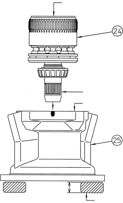
[10]Removal of cylinder assembly
Grasp the end of the cylinder (24) by hand and remove the cylinder assembly from the housing. •Oil on the cylinder (24) makes it easy for it to slide, so be careful not to let it fall. •The tapered roller bearing (3) outer race and the oil seal (2) should be left within the housing. •The "A" end surface of the cylinder is the sliding surface, so cover this surface with a soft rag, etc. to prevent scratching. •Place reference marks or numbers on the cylinder piston holes and piston assemblies (7) so that during reassembly piston assemblies are placed in the same holes they were in at disassembly.
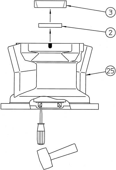
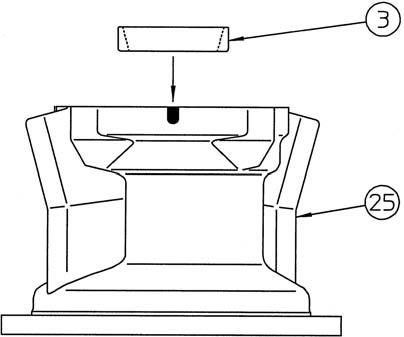
[11]Removal of tapered roller bearing outer race
Remove the tapered roller bearing (3) outer race from the housing (25).
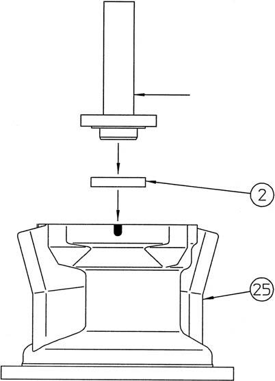
Next, strike the oil seal (2) with a screwdriver and hammer to remove it. •The oil seal cannot be reused.
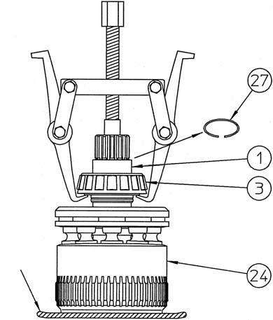
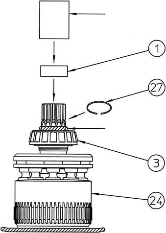
[12]Disassembly of cylinder assembly 1) Remove the inner race (1) and tapered roller bearing. Remove the snap ring (27) with the mark-off pin, use the gear puller on the two locations on the tapered roller bearing (3) inner race and the cylinder (24) spline end to remove the bearing along with the inner race (1).
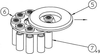
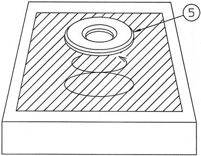
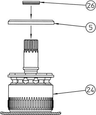
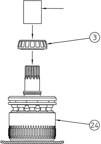
2) Remove the collar (26) from the cylinder (24). Remove the cam plate (5), return plate (6), and piston assemblies (7) all together from the cylinder.
3) Remove the cam plate (5) so that it slides on the piston assembly (7) sliding surfaces. •Be very careful with handling to prevent scratching of the cam plate or piston assembly sliding surfaces.
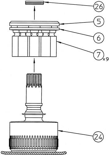
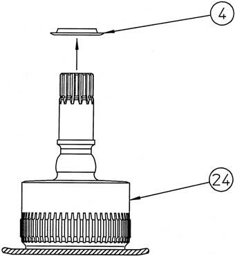
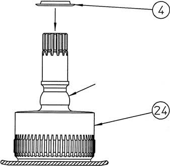
4) Remove the receiving spring (4) from the cylinder (24).
This completes the disassembly.
4.Assembly [1] Preparation before operation Execute the following preparations before reassembly. 1) Check each part for scratches from use or from disassembly. If there are any scratches, remove them with a whetstone or sandpaper of the necessary grain, clean with cleaning oil, then dry off with an air blower.
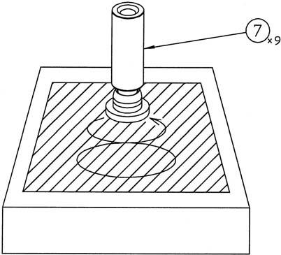
2) Replace seal parts with new ones. 3) Lap the piston assemblies (7), cam plate (5), and balance plate (21) sliding surfaces on a surface plate with #2000 sandpaper.
4) When assembling sliding sections, apply clean hydraulic oil to the parts to assemble them.
[2] Assembly of cylinder assembly 1) Apply hydraulic oil to the spherical section (interference section with receiving spring) (*1) of the cylinder (24) and install the receiving spring (4).
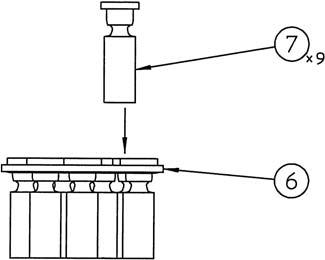
2) Insert the piston assemblies (7) into the return plate (6) holes.
3) Install the piston assemblies (7) and return plate (6) together onto the cylinder (24). •At this time, install the piston assemblies in the same holes they were in before disassembly. •When installing, apply hydraulic oil to the cylinder piston holes.
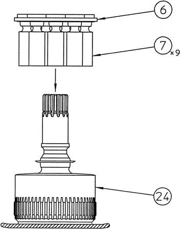
4) Apply hydraulic oil to the shoe sliding surfaces of the piston assemblies (7), and then install the cam plate (5) on the cylinder assembly (24).
Next, install the collar (26) on the cylinder assembly.
5) Use the press-fit jig 1 (*1) to install the tapered roller bearing (3) inner race on the cylinder (24) with a hand press, etc. •When press fitting, use a soft rag (*2) under the cylinder end surface to prevent scratching.
6) Clean the inner race installation section (*2) of the cylinder (24), lightly apply sealant (Loctite 515, 518, or the equivalent) after degreasing, and use the press-fit jig 1 (*1) to install the cleaned and degreased inner race (1). Next, install the snap ring (27). •Be careful not to let sealant adhere to the roller of the tapered roller bearing (3). •Thoroughly wipe off any sealant coming out from in between the inner race and tapered roller bearing.
[3] Installation of oil seal
Clean and degrease the housing (25) oil seal installation section.
Next, degrease the oil seal (2) outer circumference, apply liquid packing (ThreeBond Co.,Ltd. "1211" white or the equivalent), and use the press-fit jig 2 (*1) to install it on the housing. •Be careful to install the oil seal in the correct direction.
[4] Installation of tapered roller bearing outer race
Install the tapered roller bearing (3) outer race on the housing (25). •Be careful to install the tapered roller bearing outer race in the correct direction.
[5] Installation of cylinder assembly
Lightly apply grease to the oil seal (2) lip surface, and then grasp the sides of the cylinder (24) to gently install the cylinder assembly into the housing (25). •Oil on the cylinder makes it easy for it to slide, so be careful not to let it fall. •When installing the cylinder assembly, check that the receiving spring (4) is down in the spot facing section of the return plate (6). •When the cylinder assembly is installed, the spline shaft of the cylinder will stick out from the bottom surface of the housing, so place blocks of 30 - 40 mm (*4) under the surface. •Check that the end surface of the cylinder (*1) is sunk about 15.5 mm below the end surface of the housing (*3). If this distance is small, this means the cam plate is not completely placed in the spot facing section of the housing. Gently move the housing on its side so that the steeply diagonal side of the housing is on the bottom and lightly swing the cylinder up and down to put the cam plate in place. •When installing the cylinder assembly, place the jig 3 (*2) on the end of the spline to prevent scratching of the oil seal by the spline.
[6] Installation of friction plate and partner plate
Install the friction plates (8) and partner plates (9). •Apply hydraulic oil to both sides of each of these plates.
[7] Installation of O-ring
Attach the O-ring (10) to the housing (25).
Attach the O-ring (12) to the piston (11). •Apply grease to the O-rings.
[8] Installation of brake piston
Apply hydraulic oil to the outer circumference sliding section of the piston (11) and install it in the housing (25). •The O-ring force fits the piston, and this results in the piston being stiff during assembly. Make the entire piston level and use the installation jig 4 (*1) to press the piston down by hand in one push.
[9] Installation of spring
Install the springs (13) into the brake piston (11). •Install the springs in the same locations they were in before disassembly.
[10]Installation of balance plate
Install the bushings (20) with the Scrowave springs (18) and teflon rings (19) attached into the bushing holes on the cover (32).
Apply grease to the pistons (14) and install the pistons into the balance plate (21).
Install the balance plate on the cover. •Be careful to install in the correct direction according to the marks made on the balance plate and cover before disassembly.
[11]Installation of inner race
Press fit the needle bearing (22) inner race onto the cover (32) and install the snap ring (23).
[12]Installation of O-ring
Attach the O-ring (12) to the cover (32). •Apply grease to the O-ring.
[13]Installation of cover
Clean the matching surfaces of the cover (32) and the housing (25) and lift the cover by hand to gently install it in the housing. •Align the housing and cover using the reference mark (*1) made before disassembly. •At this time, there is a space of about 4.5 mm between the housing and cover.
[14]Bolt tightening
Install the cover (32) in the housing (25) by tightening the hexagon socket head bolts (37) to a torque of 284 N•m. •At this time, tighten each of the 4 bolts evenly a little at a time to straightly install the housing and cover.
[15]Installation of relief assembly, etc.
Install the relief assemblies (35) (14 mm hex socket diameter) into the cover (32) to a tightening torque of 78 N・m. Install the checks (38) and springs (39) into the cover and tighten the caps (40) (14 mm hex socket diameter) to the cover to a tightening torque of 137 N・m. Install the plugs (33) and caps (28) (10 mm hex socket diameter) into the cover to a tightening torque of 78 N・m. •Install the disassembled relief assemblies, caps, springs, checks and plugs so they are in their original locations.

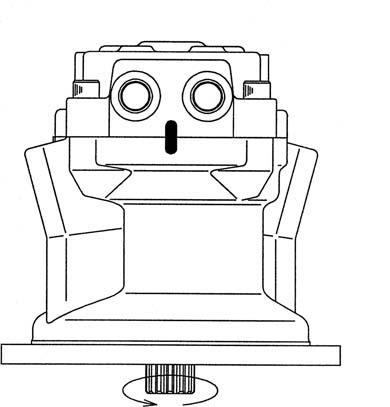
[16]Assembly confirmation
Open the input/output ports, apply 3.2 - 4.9
MPa of pilot pressure to the brake release port to check if the output shaft rotates smoothly for at least 1 rotation with about 30 - 40 N•m of torque. There is an assembly problem if it does not rotate, so disassemble the swing unit again and adjust it. •At this time, have the drain port open.
This completes the assembly.
•Check that the set pressure of the relief assembly is at the correct pressure after the hydraulic motor is installed in the actual machine.
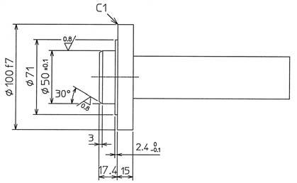
Jig 1 (For assembly of tapered roller bearing (3) and inner race (1))
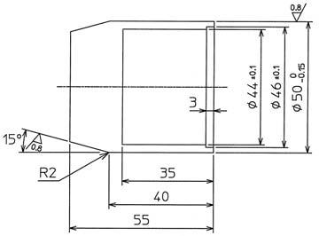
Jig 2 (For assembly of oil seal (2))
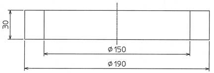
Jig 3 (For assembly of cylinder assembly (24))
Jig 4 (For assembly of brake piston (11))
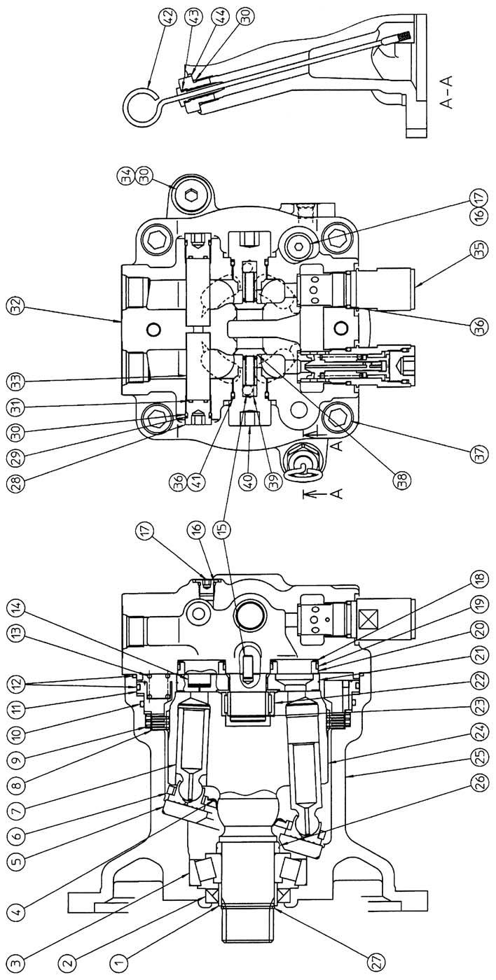
SH210-5 Swing motor internal structure diagram
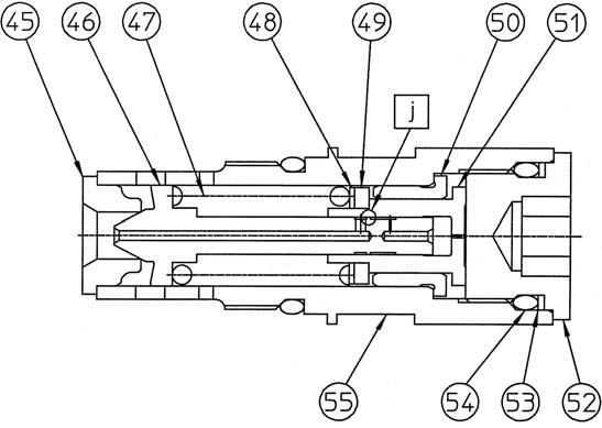
1 Inner race 2 Oil seal 3 Tapered roller bearing 4 Receiving spring 5 Cam plate 6 Return plate 7 Piston assembly 8 Friction plate 9 Partner plate 10 O-ring 11 Piston 12 O-ring 13 Spring 14 Piston 15 Parallel pin 16 O-ring 17 Cap 18 Scrowave spring 19 Teflon ring Relief internal structure diagram
20 Bushing 21 Balance plate 22 Needle bearing 23 Snap ring 24 Cylinder 25 Housing 26 Collar 27 Snap ring 28 Cap 29 Backup ring 30 O-ring 31 O-ring 32 Cover 33 Plug 34 Cap 35 Relief assembly 36 O-ring 37 Hexagon socket head bolt 38 Check 39 Spring 40 Cap 41 Backup ring 42 Level gauge assembly 43 O-ring 44 Cap 45 Seat 46 Poppet 47 Spring 48 Spring seat 49 Shim 50 Liner 51 Piston 52 Cap 53 Backup ring 54 O-ring 55 Holder
