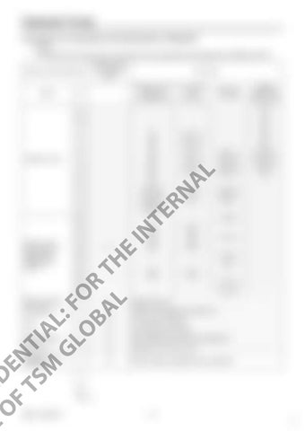
Hydraulic Pump Procedures for Assembly and Disassembly of Regulator 1. Tools The table below shows the tools required for the assembly and disassembly of KR3G-9*04-HV.
B
Hexagon socket head bolt (shouldered bolt)
Rc mounted valve (Rc screw)
ROH plug (G screw)
Hexagon socket head locking screw
2
-
-
-
M4
2.5
-
-
-
M5
3
-
-
-
M6
4
M5
BP-1/16
-
M8
5
M6
BP-1/8
-
M10
6
M8
BP-1/4
RHO-1/4
M12 M14
8
M10
BP-3/8
RHO-3/8
M16 M18
10
M12
BP-1/2
RHO-1/2
M20
12
M14
-
-
-
14
M16 M18
AL
Hexagon wrench
BP-3/4
RHO-3/4
-
17
M20 M22
BP-1
RHO-1
-
19
M24 M27
-
-
-
-
-
VP-3/8
-
M16
M16
M18
M18
M20
M20
-
-
VP-3/4
-
41
-
-
VP-1
-
46
M30
M30
-
-
50
-
-
VP-11/4
-
55
-
-
VP-11/2
-
24 27
CO US N F E ID O E F N TS TI M AL GL : F O OR BA T L H
36
○
E
30
IN
22
Closed wrench Socket wrench Double-head (single-head) wrench
Part name
RN
Name
Required tools are indicated with ○
TE
Tool name and dimensions
- VP-1/2
-
Monkey wrench
-
○
Medium-sized x 1
Screwdriver
-
○
Medium-sized flathead screwdriver x 1
-
○
For stop ring, TSR-160
-
○
For locking ring, TRR-150
Torque wrench
-
○
With adjustable specified torque tightening
Steel rod
-
○
Diameter φ4 or less L=100
Hexagon socket head bolt
-
○
M4 for pulling out adjusting ring, L=about 50
Pliers
RSM-13-09-001E
-
248 24


