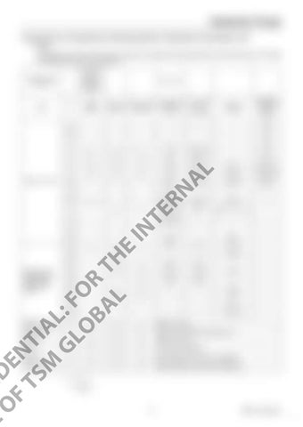
Hydraulic Pump Procedures for Assembly and Disassembly of Hydraulic Pump Main Unit 1. Tools The table below shows the tools required for assembly and disassembly of the K3V pump. The bolts and plugs may vary by pump type. Tool name and dimensions
Pump type (The ○ indicates a necessary part)
Name
K3V63 K5V80
Hexagon Rc mounted K3V112 K3V140/180 socket head valve K5V140 K5V200 bolt (Rc screw)
Hexagon socket head locking screw
-
-
-
M4
2.5
-
-
-
M5
3
-
-
-
M6
○
○
○
M5
BP-1/16
-
M8
5
○
○
○
M6
BP-1/8
-
M10
6
○
○
○
M8
BP-1/4
PO-1/4
M12 M14
8
○
○
○
M10
BP-3/8
PO-3/8
M16 M18
M12
BP-1/2
PO-1/2
M20
M14
-
-
-
M16 M18
BP-3/4
PO-3/4
AL
4
10 12 ○ ○
17
22 ○
○
E
21
19
○
IN
19
TE
14
○
○
CO US N F E ID O E F N TS TI M AL GL : F O OR BA T L H
22
Closed wrench Socket wrench Double-head (single-head) wrench
PO plug (G screw)
2
RN
Hexagon wrench
B
Part name
1/
- 11
-
M20 M22
BP-1
M24 M27
-
-
-
-
-
-
-
M30
-
PO-2
-
M12
M12
VP-1/4
-
-
-
VP-3/8
-
PO-1, 1 4,
/2
24
○
○
M16
M16
-
-
27
○
○
M18
M18
VP-1/2
-
○
M20
M20
-
-
30
○
36
○
○
-
-
VP-3/4
-
41
○
○
-
-
VP-1
-
50
-
-
VP-11/4
-
55
-
-
VP-11/2
-
Monkey wrench
-
○
○
○
Medium-sized x 1
Screwdriver
-
○
○
○
Medium-sized flathead screwdriver x 2
Hammer
-
○
○
○
Plastic hammer x 1
Pliers
-
○
○
○
For stop ring, TSR-160
Steel rod
-
○
○
○
Key material steel rod, about 10X8X200
Torque wrench
-
○
○
○
With adjustable specified torque tightening
231
RSM-13-09-001E 7


