In-Vehicle Service Procedures How to Install the Auxiliary Section in Chassis Special Instructions CAUTION
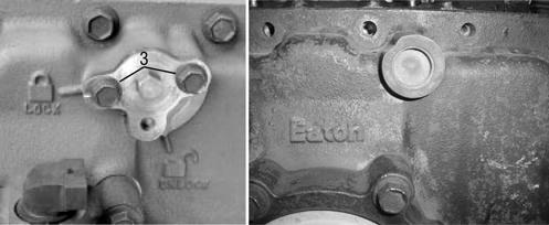
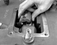
The lock cover was removed on new units, so the shiftbar housing must remain off during auxiliary assembly to attach the range cylinder.
Special Tools •
Floor Jack
•
Torque Wrench 500 lb. ft. capacity
•
Torque Wrench 100 lb. ft. capacity
•
Mounting Plate (tool ref. ID T19)
•
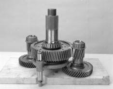
Auxiliary countershaft support tools T3
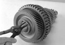
Procedure 1.
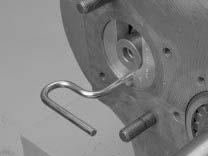
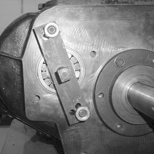
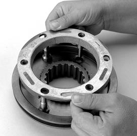
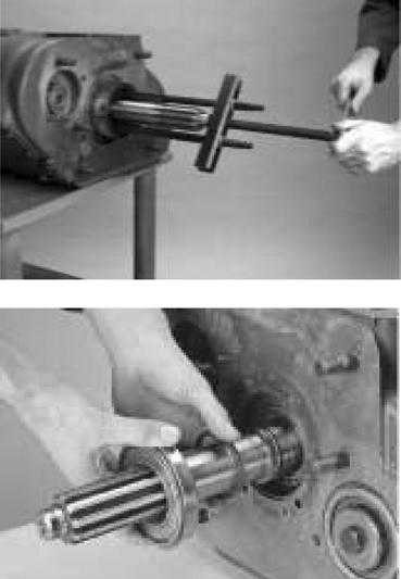
Install the countershaft support tools (Tool ref. ID T3) on the auxiliary section countershafts to center and hold the countershafts in position.
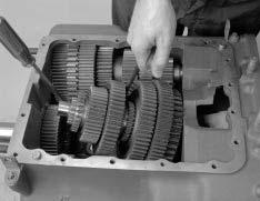
2.
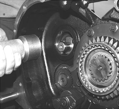
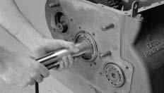
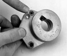
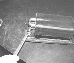
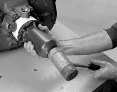
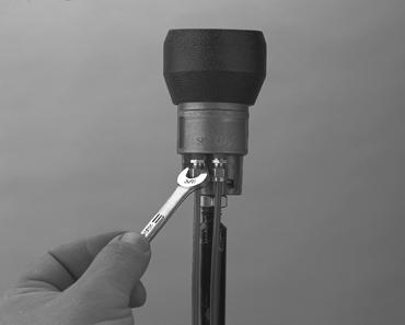
Install the output yoke over the output shaft. The yoke should slide on and stop before contacting the speedometer rotor. As the output shaft nut is installed, the output yoke will contact the speedometer rotor.
1 1
Note: To prevent the output shaft from rotating while installing the nut, place a clean shop rag in the gear mesh or use a yoke holding tool.
2
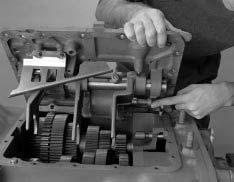
Note: Due to chassis interference, it may not be possible to install the yoke at this step. However, the output shaft must be drawn fully into position to prevent it from sagging when the auxiliary section is installed in the chassis. If the chassis causes interference, the yoke can be temporarily installed to draw up the output shaft and then removed before the auxiliary section is installed. 3.
4
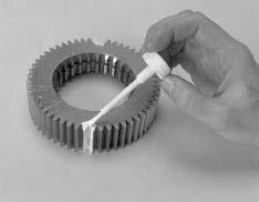
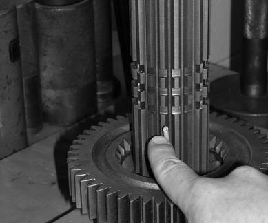
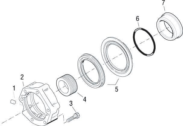
CAUTION 3/8"-1/2"
Shoulder
92
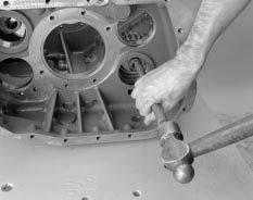
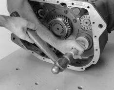
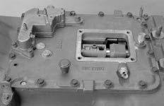
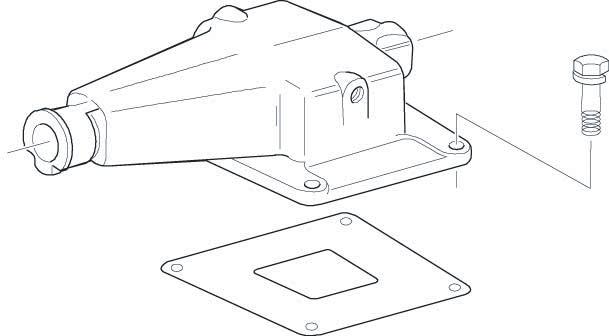
Use crocus cloth or a wire wheel to clean rust and paint from the dowel pins before installing them. If the dowel pins are not installed in the main case to the proper depth in step 4, the auxiliary section will not properly align with the main case and bearing or synchronizer failure may occur.
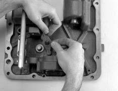
4.
Install the dowel pins into the main case so that 3/8”-1/2” of the shoulder is exposed.