3 minute read
How to Assemble the Auxiliary Section

Special Instructions
To aid in reassembling the auxiliary section, use a fixture that will hold the countershafts in the proper positions. The dimensions of the fixture are shown in the illustration. The fixture is constructed from a 2”x12”x24” piece of wood.
Special Tools
• Countershaft Retaining Straps T3
24"
3"
11.67"
Procedure -
1. For timing purposes, identify and mark with toolmaker’s dye the two teeth on each countershaft that are identified with an
“0”.
2. Place the countershafts in the fixture (or on a clean, flat surface if you don’t have a fixture) with the marked teeth turned to the middle of the fixture.
3. Position a 2” high spacer, such as a socket, between the countershafts. (If a fixture is not used, a 3” spacer is required.)
12"
2"
1
2
3
4
6
7 10
8
5

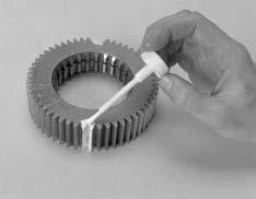
4. Install the synchronizer assembly on the output shaft. The low range synchronizer ring (side with external friction material) must be facing the auxiliary mainshaft reduction gear.
5. Match the timing marks on the auxiliary mainshaft reduction gear with the timing marks on the countershafts. The output shaft will rest on the spacer.

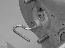
6. With the round hole in the range yoke bar facing up, slide the range yoke assembly into the groove on the range synchronizer.
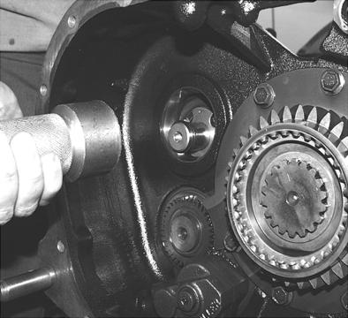
7. Lightly oil the bearing bores on the auxiliary housing, and place the auxiliary housing over the countershaft assemblies and the output shaft assembly.

8. Install the output shaft bearing race in the housing bore.
9. Make sure the output shaft bearing inner spacer is on the output shaft. (The spacer should have been installed when the output shaft components were assembled.)
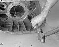
10.Heat the rear output bearing cone (or use an appropriate driver) and install the outer bearing cone, tapered side down, on the shaft.
11.Install a new gasket.
12.Using the marks made during disassembly as a guide, install the rear bearing cover in the same position as when removed.
Note: The rear bearing cover can be installed in two positions opposite each other. If the rear bearing cover is not installed in the same position in which it was removed, the speedometer cable may not reach the speedometer after the transmission is installed in the vehicle. If the speedometer cannot be connected, the auxiliary bearing cover must be removed and reassembled properly.
13.Apply Eaton®Fuller® Sealant #71205 or equivalent to the six (6) rear bearing cover retaining capscrews and install them. Tighten the capscrews to 40-45 lb. ft. (54-61 N•m) of torque.
14.Insert the countershaft bearing races in their bores.
Note: If the original parts are being reused and installed in their original locations, the shims can also be installed at this time.
15.If shimming will be required, temporarily install the auxiliary countershaft shim and support tools (Tool ref. ID T3). Final installation and shimming of the countershafts will be done after the auxiliary section is installed on the front section.
Note: If shimming will not be required, the auxiliary countershaft bearing covers can be installed at this time. However, the shim tools will help prevent the countershafts from dropping excessively when the auxiliary section is installed.
16.If desired, secure the auxiliary section in a vise with brass jaw protectors. 12


15
14
15
17
19
18
CAUTION
New units don’t contain the lock cover, so the shift bar housing must remain off until the auxiliary section and range cylinder are assembled.
18.Install the O-ring over the output shaft, and insert it against the output bearing.
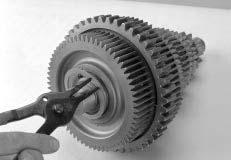
19.Install the speedometer rotor/seal sleeve.
20.Install the output yoke over the output shaft. The yoke should slide on and stop before contacting the speedometer rotor. As the output shaft nut is installed, the output yoke will contact the speedometer rotor.
21.Inspect the output nut for damage and wear. If the nylon locking material is damaged or excessively worn, use a new output nut.
Note: The nylon locking material must be in good condition to prevent the nut from loosening during operation.
22.Lightly oil the output shaft threads and the output nut threads and install the nut. Torque the nut to 450-500 lb. ft. (610-677 N•m).
17.On the auxiliary housing back, install the range alignment lock cover and O-ring. Rotate the cover to the unlock position, and secure the cover in place with a capscrew.