3 minute read
Section in ChassisHow to Remove the Auxiliary


How to Remove the Auxiliary Section in Chassis
Special Instructions
The following procedure covers the removal of the auxiliary section with the transmission remaining in the chassis. If the transmission has been removed, refer to “Auxiliary Section Removal (Bench Procedure)” for removal procedures.
CAUTION: The lock cover was removed on new units, so the shiftbar needs to be removed to unlock the range cylinder and remove the auxiliary section.
Special Tools
• Floor Jack • M10 x 1.5 tap • Mounting Plate T19 (see Table 6)
Procedure -
Roadranger¨ Valve 1. Place the range selector on the shift knob in the down position to shift the transmission into low range. Removing the auxiliary section when the transmission is in Low Range will aid in reassembly.
2. Drain the transmission oil.
3. Disconnect the driveshaft and U-joint from the output yoke.
4. If the auxiliary section is to be disassembled, remove the output nut using a 70 mm or 2 3/4” socket. To prevent the output shaft from rotating while removing the nut, shift the transmission to 1st gear or use a yoke holding tool.
Jam Nut WARNING
If the shift bar housing is still installed, you MUST perform steps 5 and 6 if the lock cover is present. New designs no longer use the lock cover and the shiftbar housing must be removed for auxiliary section removal.
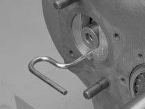
5. Remove the capscrews from the range bar lock cover, and rotate the lock cover counterclockwise until the notch on the cover lines up with the unlock symbol.
Note: The left is the old style cover and the right is the new style cover.
Note: If the system still contains air pressure, greater force is required to turn the lock cover.
6. Insert the right capscrew to secure the cover in the unlock position.
Note: This step unlocks the range yoke bar in the auxiliary from the range piston bar in the shift bar housing.
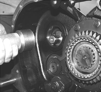
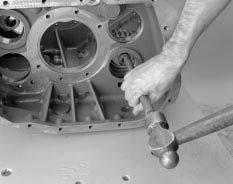
7. Drive the two dowel pins forward, and remove them.

8. Remove 18 of the 19 capscrews that secure the auxiliary section to the main section. Leave one capscrew to secure the housing until it is ready to be removed.
Note: Capscrews are different lengths. Note their locations for reassembly purposes.
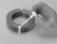
9. Clean and oil the three threaded pusher holes in the auxiliary section flange. To clean them, thread an M10x1.5 tap into each hole to remove paint, rust, and other debris.
WARNING
Use the proper equipment with safety chains attached to remove the auxiliary section. The auxiliary section can slide rearward and could fall, causing you serious injury and/or damage to the auxiliary section.
10.Attach the chain and lifting device to the auxiliary section hanger, or attach the support jack to the auxiliary section. (Tool ref. ID T19).
Remove the rear bearing covers and install the Auxiliary countershaft shim/retaining plates T3.
11.Thread capscrews into each of the three previously cleaned pusher holes in the auxiliary section flange. Run the capscrews in evenly to break the gasket seal and move the auxiliary housing rearward approximately 1/4.” After breaking the gasket seal, remove the pusher screws.
CAUTION
The weight of the auxiliary section must be supported during removal to avoid damage to the range yoke bar.
12.Support the weight of the auxiliary section with the lifting device or support jack and move the auxiliary section rearward until it is free from the front section of the transmission. 9
7
8 9 9
7
1
2 1