2 minute read
How to Remove the Mainshaft Assembly


Special Instructions
If transmission service will be limited to removal of the mainshaft, the input shaft does not need to be removed, but it must be moved forward to provide enough clearance to remove the mainshaft.
Special Tools
• Item T8: Countershaft Pusher • Item T9: Bearing Puller • Mainshaft Hook Tool T20 (see Table)
Main Case
Gasket Input Bearing Cover Capscrew (x6)
Procedure -
1. Remove the six (6) capscrews retaining the input bearing cover, and remove the cover as shown in the explode view.
2. Grasp the input shaft and pull it forward until the main drive gear contacts the case wall.
3. From the mainshaft, remove the reverse gear retaining snap ring. 2

3 5
4

4. Rotate the mainshaft reverse gear to engage the sliding clutch, and then move the gear forward over the sliding clutch to a position flush with the next gear on the mainshaft.
5. From the mainshaft, remove the tanged washer.
6. Lift out and remove the upper reverse idler gear.
7. Remove the countershaft front and rear bearings using the following procedure: a. Grasp the mainshaft and pull rearward until the reverse gear is against the case wall. b. Remove the snap rings from the rear of the countershaft.
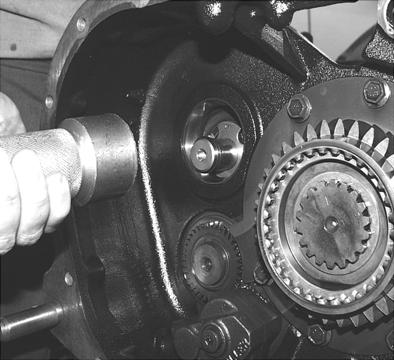
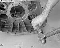
Note: To prevent part damage, Eaton® recommends using a hand tool to operate the bearing removal tool in step c. rather than an air powered tool. c. Install the bearing pusher tool on the front countershaft bearing (Tool ref. ID T8) in the main case as shown. Use the tool to push the countershaft rearward through the front bearing. Move the countershaft slowly, and stop when resistance is felt. d. If necessary, repeat steps a. through c. with the lower countershaft.
Note: The lower countershaft does not need to be removed to remove the mainshaft.
e. Remove the lower tool T8 from the front countershaft. f. Attach the bearing puller (Tool ref. ID T9) to the upper countershaft rear bearing as shown, and remove the bearing. g. If the front of the countershaft is still in the front bearing, drive the countershaft forward to expose the front bearing snap ring. Then use the bearing puller (Tool ref.
ID T9) to remove the bearing. h. If necessary, repeat this procedure for the lower countershaft bearings.

8. Insert a large screwdriver between the main drive gear and the upper countershaft driven gear to hold the countershaft to the side and away from the mainshaft.
9. Make sure the mainshaft reverse gear is moved forward and held against the next gear (1st speed gear).
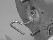
10.Position the mainshaft hook tool (Tool ref. ID T20) or rope around the mainshaft.

Note: Keep the upper countershaft forward against the case front wall.
11.Pull the mainshaft to the rear to free the pilot from the input shaft pocket.
WARNING
Be careful when removing the mainshaft assembly. The sliding clutch on the front and the reverse gear on the back can slip off the shaft.
12. Tilt the mainshaft front up and lift the assembly from the case. 8 10