2 minute read
How to Install the Auxiliary Section


Special Instructions
Use crocus cloth to clean the dowel pins and dowel pin holes of all paint and corrosion. Apply a light coating of grease to the dowel pin holes.
Special Tools
• Lifting Device • Auxiliary Section Hanger Bracket T2 (see Table 6) • Torque Wrench 50 lb. ft. capacity • Torque Wrench 500 lb. ft. capacity • Auxiliary Countershaft Support Plates T3
Procedure -
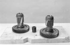
1. If not previously installed, install the output yoke (or flange) and the output nut. The yoke should slide on and stop before contacting the speedometer rotor. As the output shaft nut is installed, the output yoke will contact the speedometer rotor.
Torque the output nut to 450-500 lb. ft. (610-677 N•m).
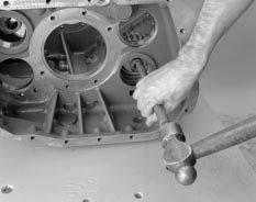
2. Install the dowel pins to the proper depth. (3/8” to 1/2” of the shoulder on the pins must be visible.)
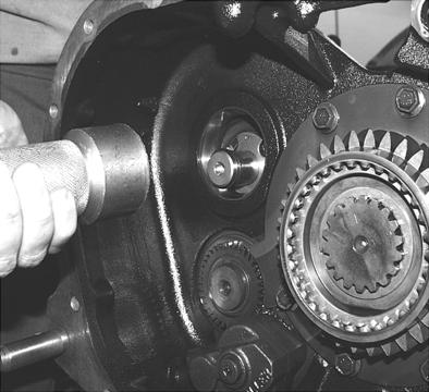
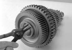
3. Make sure the auxiliary section is in low gear. If it is not, use one or two large screwdrivers or prybars to apply even rearward pressure to move the range sliding clutch back into the low gear position.
4. Make sure the Auxiliary Countershaft plates are installed.
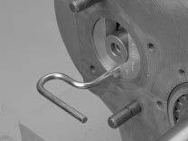
5. If the shift bar housing is installed, make sure the range bar lock cover is rotated counterclockwise into the unlock position. 2
3/8"-1/2"
Shoulder
3
CAUTION
New units have removed the lock cover, so the shiftbar housing must remain off until the range cylinder and auxiliary sections are assembled.
4
6
CAUTION
Do not force or pull the auxiliary section into position with capscrews when sliding it into place. It should slide into place fairly easily. If excessive force is necessary, the countershafts are drooping or the gearing is not in proper mesh, remove the auxiliary section and try again.
10.Slide the auxiliary section fully into position.
11.Apply Eaton®Fuller® thread sealant #71205 to the capscrew threads, and install the 19 capscrews. Torque them to 40-45 lb. ft. (54-61 N•m)
12.Remove the capscrew securing the range bar lock cover in the unlock position and rotate the cover to the lock position.
Insert the two capscrews to secure the lock cover in position. Torque them to 20-23 lb. ft. (27-31 N•m).
Note: To properly align the lock cover, the auxiliary section must be in low range when the capscrews are tightened.
13.Remove the auxiliary countershaft rear bearing covers, and shim the countershafts using the procedure on the following page.
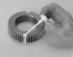
6. Position the gasket on the main case mounting surface.
7. Attach the auxiliary section hanger bracket to the top of the auxiliary section, and attach the chain of the lifting device to the bracket. (Tool ref. ID T2)
8. Allow the lifting device to support the weight of the auxiliary section, and position the auxiliary section on the two dowel pins. Slide the auxiliary section forward.
Note: The range yoke bar must slide into the bore in the main case.
Note: To help the auxiliary countershafts mesh with the auxiliary drive gear, rotate the output yoke to turn the gearing.
Note: If the auxiliary countershafts drop excessively, the auxiliary countershaft shim tools (Tool ref. ID T3) can be used to support the countershafts.
Note: The auxiliary section can be assembled to the transmission with the transmission in the vertical position.
9. Remove the auxiliary section hanger bracket.