5 minute read
sHow to Install the Auxiliary Section in Chassi


How to Install the Auxiliary Section in Chassis
Special Instructions
CAUTION
The lock cover was removed on new units, so the shiftbar housing must remain off during auxiliary assembly to attach the range cylinder.
Special Tools
• Floor Jack • Torque Wrench 500 lb. ft. capacity • Torque Wrench 100 lb. ft. capacity • Mounting Plate (tool ref. ID T19) • Auxiliary countershaft support tools T3
1
2
4
3/8"-1/2"
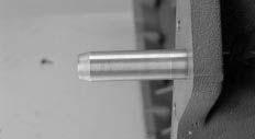
Shoulder 1
Procedure -
1. Install the countershaft support tools (Tool ref. ID T3) on the auxiliary section countershafts to center and hold the countershafts in position.
2. Install the output yoke over the output shaft. The yoke should slide on and stop before contacting the speedometer rotor. As the output shaft nut is installed, the output yoke will contact the speedometer rotor.
Note: To prevent the output shaft from rotating while installing the nut, place a clean shop rag in the gear mesh or use a yoke holding tool.
Note: Due to chassis interference, it may not be possible to install the yoke at this step. However, the output shaft must be drawn fully into position to prevent it from sagging when the auxiliary section is installed in the chassis. If the chassis causes interference, the yoke can be temporarily installed to draw up the output shaft and then removed before the auxiliary section is installed.
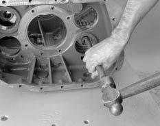
3. Use crocus cloth or a wire wheel to clean rust and paint from the dowel pins before installing them.
CAUTION
If the dowel pins are not installed in the main case to the proper depth in step 4, the auxiliary section will not properly align with the main case and bearing or synchronizer failure may occur.
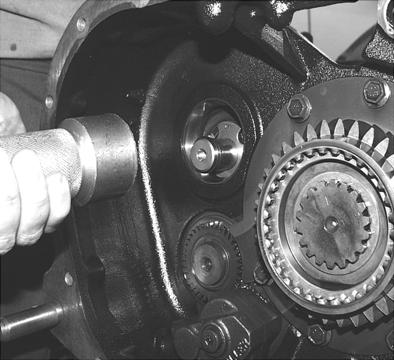
4. Install the dowel pins into the main case so that 3/8”-1/2” of the shoulder is exposed.
5. Clean all rust and paint from the dowel pin holes in the auxiliary section housing, and lightly grease the dowel pins on the main case and the dowel pin holes on the auxiliary section housing.
6. Make sure the auxiliary section is in low range. If not, use one or two large screwdrivers or prybars to apply even rearward pressure to the range sliding clutch to move it into the
Low Range position.
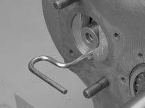
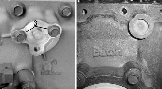
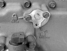
7. Make sure the range bar lock cover is in the unlock position.
If not, rotate it counterclockwise until the notch on the cover is aligned with the unlock symbol, and secure it in that position. 6
CAUTION
The lock cover has been removed on newer models, so the shiftbar housing needs to remain removed until the range cylinder and auxiliary section are assembled.
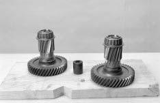
Note: Old style auxiliary cover on the left and new style cover on the right.
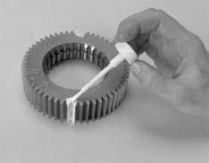
8. Position the gasket onto the main case mounting surface.
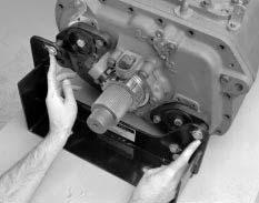
9. Mount the auxiliary section on the lifting device or jack. (Tool ref. ID T19).
10.Tighten the center capscrew on the countershaft support tools to draw the countershafts into a level position. Do not overtighten the capscrews. The output yoke and shaft must be able to rotate.
11.Position the auxiliary section in line with the main case, and perform the following steps: a. Insert the range yoke bar into the bore. b. Mesh the countershafts with the auxiliary drive gear. Rotate the output yoke and shaft slightly to help the gears mesh. 10
9 10
15
CAUTION
The auxiliary section should slide into place fairly easily. DO NOT force it on or pull it into place with the capscrews. Excessive force may damage the transmission. If excessive force is necessary, the gearing is likely out of time. Remove the auxiliary section, tighten the countershaft support tools, and try again.
12.While rotating the output shaft, slide the auxiliary section forward as far as it can go.
13.Apply Eaton®Fuller® thread sealant #71205 or equivalent to the capscrew threads.
14.Install the 19 retaining capscrews to secure the auxiliary section to the main case. Torque the capscrews to 40-45 lb. ft. (54-61 N•m).
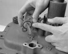
15.Remove the capscrew securing the range bar lock cover in the unlock position, and remove the lock cover. Check the Oring on the inside of the cover to be sure it is in position, and look for signs of wear or damage. Replace it if necessary.
Apply Eaton®Fuller® thread sealant #71205 or equivalent to the capscrews used to secure the cover.
16.Install the range bar lock cover, and rotate it clockwise until the notch on the cover aligns with the lock symbol.
Note: The cover should rotate fairly easily. If it does not rotate, the range piston bar and the range yoke bar may not be in the same range position (low range). Move the range lever from low to high and back to low, while rotating the lock cover.
17.Secure the cover in the locked position with the capscrews, and torque them to 20-23 lb. ft. (27-31 N•m).
Note: To properly align the lock cover the transmission must be in Low Range prior to tightening the capscrews.
16
17
18.If the countershaft, countershaft bearings, or auxiliary housing have been replaced, or if the countershafts, bearings, or shims were not marked and reassembled in the same location, the bearing endplay must be checked and set by shimming. Shim the countershaft bearings using the shim procedure in Transmission Overhaul Procedure-Bench Service.
19.If shimming is not required, remove the support tools, and install the original shim in the proper location, new gasket and countershaft bearing cover. Secure the bearing covers with the capscrews. Tighten the capscrews to 40-45 lb. ft. (54-61 N•m)
20.Connect the driveshaft and U-joint, and refill the transmission with the recommended lubricant. For lubrication instructions refer to the Lubrication section of this manual.