In-Vehicle Service Procedures How to Remove the Auxiliary Section in Chassis Special Instructions The following procedure covers the removal of the auxiliary section with the transmission remaining in the chassis. If the transmission has been removed, refer to “Auxiliary Section Removal (Bench Procedure)” for removal procedures. CAUTION: The lock cover was removed on new units, so the shiftbar needs to be removed to unlock the range cylinder and remove the auxiliary section.
Special Tools •
Floor Jack
•
M10 x 1.5 tap
•
Mounting Plate T19 (see Table 6)
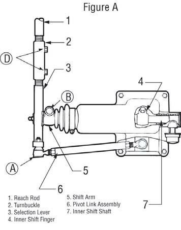
Procedure Roadranger¨ Valve
1.
Place the range selector on the shift knob in the down position to shift the transmission into low range. Removing the auxiliary section when the transmission is in Low Range will aid in reassembly.
2.
Drain the transmission oil.
3.
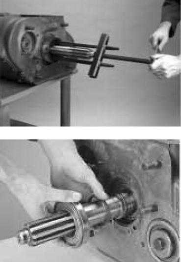
Disconnect the driveshaft and U-joint from the output yoke.
4.
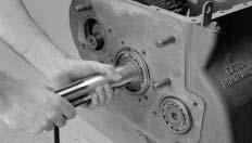
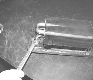
If the auxiliary section is to be disassembled, remove the output nut using a 70 mm or 2 3/4” socket. To prevent the output shaft from rotating while removing the nut, shift the transmission to 1st gear or use a yoke holding tool. WARNING
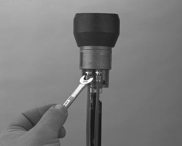
Jam Nut
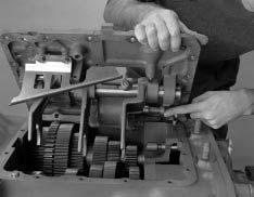
If the shift bar housing is still installed, you MUST perform steps 5 and 6 if the lock cover is present. New designs no longer use the lock cover and the shiftbar housing must be removed for auxiliary section removal. 5.
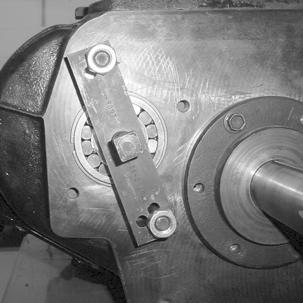
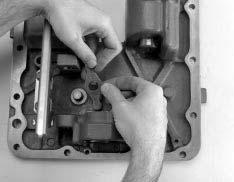
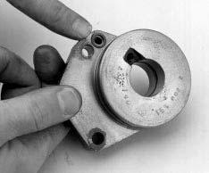
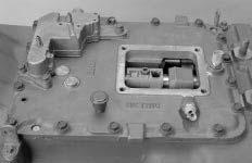
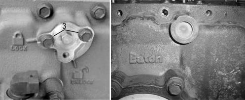
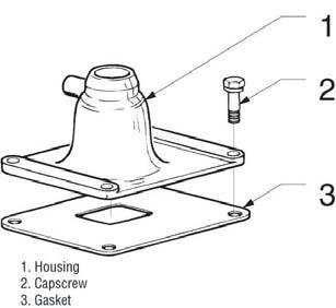
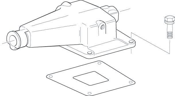
Remove the capscrews from the range bar lock cover, and rotate the lock cover counterclockwise until the notch on the cover lines up with the unlock symbol. Note: The left is the old style cover and the right is the new style cover. Note: If the system still contains air pressure, greater force is required to turn the lock cover.
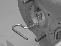
6.
90
Insert the right capscrew to secure the cover in the unlock position.