In-Vehicle Service Procedure How to Adjust the Remote Shift Control (LRC Type) Special Instructions The following is a typical adjustment procedure for an LRC type slave control. It is recommended that the OEM Chassis Service Manual be consulted first.
Special Tools •
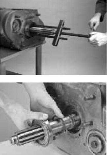
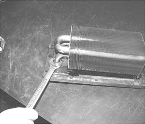
Typical service tools
Procedure 1.
Move the gear shift lever forward or backward to the neutral position.
2.
Move the gear shift lever sideways, toward reverse, until you feel resistance from the reverse plunger spring. DO NOT shift to reverse. The shift finger must remain in this position while you are making all the adjustments.
3.
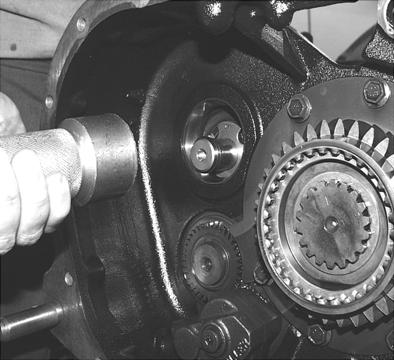
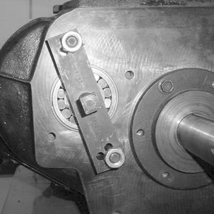
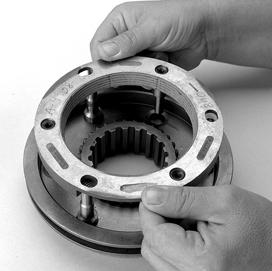
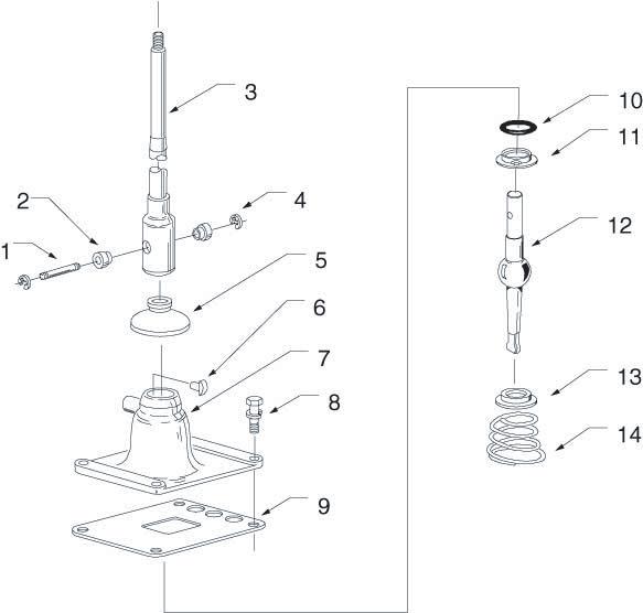
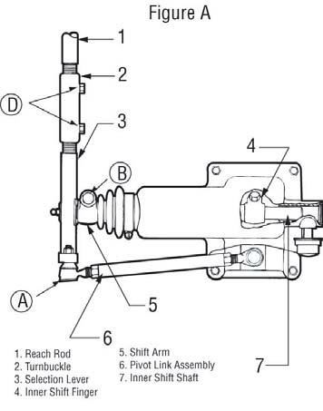
Remove the cotter pin, castle nut and ball joint A (see figure A) from the selection lever. Do not remove the ball joint from the pivot link.
4.
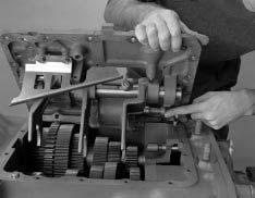
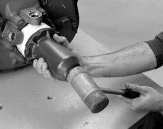
Loosen the capscrew B (see figure A) and remove the shift arm from the inner shift shaft. Do not disconnect the selection lever from the shift arm.
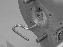
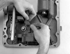
5.
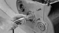
Turn the shift arm until it is at a right angle (90°) to the selection lever as viewed from the side (see figure B). Note: Ideally, the shift arm should be adjusted 90° to the selection lever as described, but in some chassis configurations it may be necessary to index the shift arm in the vertical position. Indexing the shift lever is done to prevent shift lever jump out. This type of adjustment will cause an unequal amount of gear shift lever travel between neutral and a forward lever position as compared to neutral and a rearward lever position.
74