Eaton Fuller Heavy Duty FR FRO Transmissions TRSM2400 Service Manual - PDF DOWNLOAD

Page 35

Air System Troubleshooting

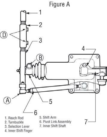
The symptoms listed below are covered on the following pages. Before beginning any of those troubleshooting procedures, place the transmission in neutral and move the range selection lever from low to high. Listen for any constant air leak from the shift knob, air module base (exhaust), or transmission breather. If a constant leak is heard, go to that particular leak troubleshooting procedure first. If you do not see the symptom you need to correct, refer to the General Troubleshooting chart. Symptom •

Air Leak from Air Module Base (Exhaust Leak)

No or Slow Range Shift into High (Shift into low range is good)

No or Slow Range Shift into Low (Shift into high range is good)

Constant Air Leak from Shift Knob

Range Shifts in Gear

Air Leak from Transmission Breather or Transmission Case is Pressurized

Note: Use the air system troubleshooting procedures for part replacement only if the symptom can be duplicated. If the problem is intermittent, parts that are not defective could be replaced. Note: During all testing, the vehicle air pressure must be greater than 90 PSI (620 kPa). If during testing the pressure falls below 90 PSI (620 kPa), make sure the transmission is in neutral, start the engine and let the pressure build to governor cutoff. After the pressure reaches the governor cutoff, continue testing. The pressure is critical if the vehicle is equipped with a vehicle air system Pressure Protection Valve that would shut off the air supply to certain air circuits if the system pressure dropped below a preset level. Note: A 0-150 PSI (0-1034 kPa) air gauge with a 1/16" male pipe thread fitting attachment is required for some of the test procedures. Note: Regulated air pressure is 75 to 85 PSI (517 - 586 kPa). WARNING

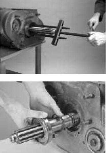
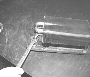
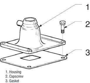
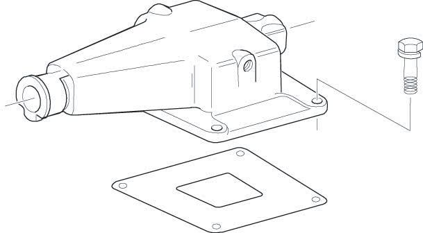
Prior to removing the air module, exhaust the air from it. Failure to exhaust the air module may result in personal injury or damage to parts from the sudden release of air. Use care when removing the test port pipe plugs. If air pressure is present on the plug, it can become a projectile during removal. When removing the “L” plug or “H” plug, pressure can be shut off by selecting the opposite range mode. If removing the “F” plug, exhaust the air to the module inlet.

31

General Information

Air System Troubleshooting


Turn static files into dynamic content formats.

Create a flipbook

Articles inside

How to Install the Auxiliary Section

2min
pages 191-192

Shim Procedure without a Shim Tool for Tapered Bearings

3min
pages 193-196

How to Assemble the Auxiliary Section

3min
pages 187-190

Gear Assembly

1min
pages 179-180

How to Install the Upper Countershaft Bearings

2min
pages 177-178

Drive Gear

1min
pages 174-175

How to Install Countershaft Assemblies

1min
page 171

How to Install the Input Bearing Cover

1min
page 176

Gear Assembly

1min
pages 169-170

How to Assemble the Countershaft Assemblies

2min
pages 167-168

How to Install the Mainshaft Assembly

1min
pages 165-166

Tolerance Washers

2min
pages 162-164

Case for ReassemblyHow to Prepare the Main

1min
page 159

ft AssembliesHow to Remove the Countersha How to Disassemble the

1min
pages 153-154

How to Remove the Mainshaft Assembly

2min
pages 150-152

How to Remove the Upper and Lower Countershaft Bearings

1min
pages 148-149

How to Assemble the Synchronizer Assembly

1min
pages 134-135

How to Install the Auxiliary Countershaft Bearing Races

1min
page 142

hronizer AssemblyHow to Disassemble the Sync

1min
page 133

How to Remove the Auxiliary Section

2min
pages 126-127

How to Assemble the Shift Bar Housing .... How to Remove the Input Shaft Assembly

4min
pages 118-121

without main case disassembly

1min
pages 124-125

How Assemble the Range Cylinder

1min
pages 116-117

without main case disassembly) How to Install the Input Shaft Assembly

1min
pages 122-123

How to Install the Shift Bar Housing

1min
page 111

How to Remove the Shift Bar Housing

1min
page 110

How to Assemble the Gear Shift Lever

1min
pages 108-109

How to Disassemble the Gear Shift Lever

1min
pages 106-107

How to Assemble the Integral Oil Cooler

1min
page 102

sHow to Install the Auxiliary Section in Chassi

5min
pages 96-99

Speedometer How to Install the Oil Seal Mechanical/Magnetic

2min
pages 90-91

Section in ChassisHow to Remove the Auxiliary

3min
pages 94-95

Speedometer

1min
pages 92-93

How to Remove the Shift Bar Housing Ho to Remove the Oil Seal Mechanical/Magnetic

1min
page 89

How to Install the Shift Bar Housing

1min
page 88

How to Remove the Reverse Switch

1min
page 86

Reverse Switch Operation and Testing

1min
page 85

How to Remove the Neutral Switch

1min
page 83

How to Adjust the Remote Shift Control (LRC Type

2min
pages 78-79

How to Install the Detent Spring

1min
page 81

How to Remove the Gear Shift Lever/Remote Shift Control

1min
page 76

Shift Control

1min
page 77

How to Install a Roadranger Valve

1min
page 75

How to Install Compression Type Fittings

1min
page 71

Type FittingsHow to Install Push-To-Connect

1min
page 73

Timing Procedures

1min
pages 64-65

Air System Troubleshooting

18min
pages 35-45

General Troubleshooting Chart

3min
pages 46-48

Oil Leak Inspection Process

1min
page 14

Tool Specifications

5min
pages 19-22

Torque Specifications

1min
pages 23-24

Lubrication Specifications

1min
pages 12-13

Serial Tag Information and Model Nomenclature

2min
pages 9-11

Purpose and Scope of Manual

7min
pages 5-8
Issuu converts static files into: digital portfolios, online yearbooks, online catalogs, digital photo albums and more. Sign up and create your flipbook.
Eaton Fuller Heavy Duty FR FRO Transmissions TRSM2400 Service Manual - PDF DOWNLOAD by www.heydownloads.com - Issuu