Electrical systems – 5000 Functional description T-code 787, 788
Valid from serial number 931876-
Date 2006-04-10
Order number 232370-040
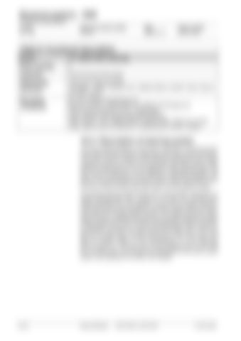
Table 9: Functional description Event:
13. Initial forks lowering
Prior event(s)
2
Action(s)
Press the lower forks button
Influencing elements
Forks lower button [A2:S22] Lift height < 100mm, S32 [A1:INP. CABIN/FORKS LOWER THAN 100mm] activated (option)
Resulting conditions
[A1:OUT.LOWER VALVE] goes low [A36:OUT.INITIAL FORKS SOFT CLOSING VALVE] goes low Forks lowering hydraulic valve [Y10] activates. Cabin hydraulic soft closing valve [Y69] activates. When S32 [A1: INP. CABIN/FORKS LOWER THAN 100mm] is not activated, pallet to ground protection or footprotection is active. (option)
10.4.1 Description of steering system The servo steering system on this truck comprises a synchronous DC motor (M6) with permanently magnetized rotor which is also brushless. This type of motor is ideal for truck steering applications due to light weight and high torque even from stand still. The motor directly drives the drive wheel gear unit, via an integrated 2 stage planetary gear. The steer motor is controlled by a fully electronic 4-quadrant regulator (A5) which is mounted directly in the servo motor casing. Hall sensors (H) in the servo motor provide timing information for commutation control. The sensors also provide the steer servo with position information. A double potentiometer (R2) mounted in the tiller unit provides steer angle information from the operator. Every time the traction battery is connected and the truck switched on the steer system performs a reference search for "straight ahead" position. An inductive proximity switch (S65) mounted in the final drive gear mounting plate registers a change in state (either ON to OFF or OFF to ON depending on drive wheel's initial position) and feeds this signal back to the steer servo. From this point on, the steer servo "knows" the position of the drive wheel. Only efter the traction battery is next disconnected, is a new reference search carried out. The steer servo communicates fully via the CAN bus. All steer servo errors codes are transmitted to the truck's control system and displayed on the tiller unit's display.
10- 24
Service Manual
7LOP10CW, 7LOP10CF
© TIEE SARL


