2 minute read
Electrical steering system – 4300


Disassembly/assembly
T-codeValid
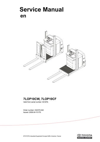
9.4 Disassembly/assembly of pushbuttons
•Disassemble the keypad.
•While taking hold of the top cover, remove the screws.
•Disconnect the cable that is connected to the logic card.
•Remove the screws.
•Carefully lift out the lower cover, while holding a finger between the lower cover and the pushbutton in order to keep the pushbutton in place.
Assembly is done in reverse.
NOTE!
Static electricity! Risk of static discharge that can damage the electronic modules. Before commencing work on the electronic modules, be sure to take the necessary measures.
9.4.1 Replacing the hornbutton/switch
•Disassemble the pushbutton as shown in the picture.
•Disconnect the switch connector on the logic card.
•Press out the switch from its holder. Assembly is done in reverse.
•Remove the pushbutton by inserting a flat screwdriver into the slot (A) as shown in the picture below.
9.4.2 Replacing the lifting/lowering pushbutton
•Insert a screwdriver in the slot as shown in the picture and carefully pry loose the pushbutton.
•Unscrew the holder to loosen the arm. Assembly is done in reverse.
9.4.3 Replacing the pushbutton
•Press out the pushbutton laterally with the fingers.
•Unscrew the pushbutton holder and arm. Assembly is done in reverse.
Electrical steering system – 4300
Replacing the potentiometer
T-codeValid from serial numberDateOrder number 787, 788931876-2006-04-10232370-040
9.5 Replacing the potentiometer
•Disassemble the rear cover (A) where the emergency stop switch is situated.
•Undo the connection block (B) from the emergency stop switch by depressing the locking device on the connection block.
•Separate the switch at the Ergo arm (C) and pull the entire cable assembly mount straight up.
Electrical steering system – 4300
•Disassemble the pivot covers (D, E) and the keypad.
Electrical steering system – 4300
Replacing the potentiometer
T-codeValid from serial numberDateOrder number 787, 788931876-2006-04-10232370-040
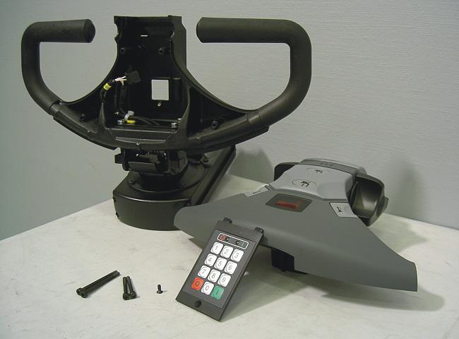
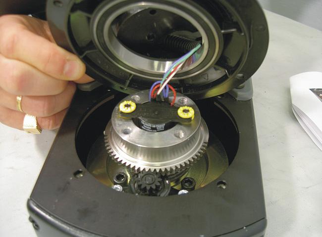
•Disassemble the top cover and cut off the two bundling cords securing the cable. NOTE! It is important to place new bundling cords at the same places where the old ones were removed.
•Undo the cable clamp and lift the potentiometer and its cabling straight up.
•Assembly is done in reverse. NOTE! It is important that clamps and bundling cords are placed at the same positions as prior to disassembly. After complete assembly, calibrate the steering using parameters 36 and, if necessary, also parameter 37.
Electrical steering system – 4300
9.6 Replacing the inductive brake sensor
•Disassemble the pivot arm covers (A)
•Disassemble the keypad and the top cover of the steering unit.
Electrical steering system – 4300
Replacing the inductive brake sensor T-codeValid
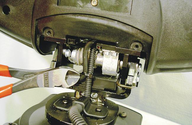
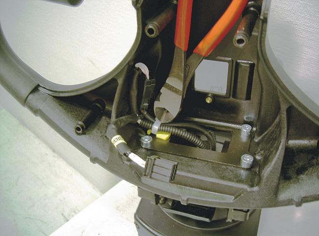
•Cut off the bundling cords and separate the switch (A). NOTE! It is important to place new bundling cords at the same places where the old ones were removed.
•Loosen the screw that holds the sensor in place and lift it straight up. The sensor has a guide pin on the rear side.

Electrical steering system – 4300
Replacing the inductive brake sensor
Electrical steering system – 4300
Replacing the viscous damper
T-codeValid
9.7 Replacing the viscous damper
•Disassemble the pivot arm covers (A)
•Disassemble the cable camp and the pivot arm covers, and loosen the 4 screws (B)

Electrical steering system – 4300
Replacing the viscous damper
Order numberDateValid from serial numberT-code 232370-0402006-04-10931876-787, 788
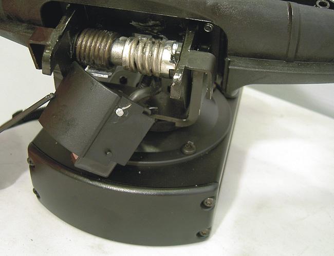
•Loosen the screws that hold the ring in place and gently pry loose the steering head. The steering head can then be slanted across the motor compartment.
•Remove the screws of the viscous damper and the spacer.

Electrical steering system – 4300
Replacing the viscous damper