8 minute read
Maintenance


Safety rules during maintenance work
•The truck is equiped with a fan for cooling the electronic system. This fan keeps running as long as the main contactor (K10) is activated. Touching the turning fan can injure fingers, hand.
•Use paper or a thick paper board to inspect possible hydraulic oil leaks. Do NOT use your hand.
•Keep in mind that the transmission oil and hydraulic system oil may be burning hot.
WARNING!
Risk of burn injuries. Hot transmission and hydraulic oil. Allow the truck to cool down prior to replacing the oil.
•Use only new and clean oil when refilling the hydraulic oil system.
WARNING!
Risk of damaging the hydraulic system. If the oil is contaminated, the hydraulic system components will be damaged.
Always use new and clean oil in the hydraulic system.
•Store and transport replaced oil in accordance with local regulations.
•Do not flush solvents, etc. used for cleaning into drains that are not specifically suited for this. Follow local regulations with regards to destruction of oil, solvents, etc.
•Disconnect the battery prior to performing welding work on the truck.
NOTE!
The battery could become damaged. When using an electric welding system, the welding current could reach the battery. Be sure to first disconnect the battery.
•Prior to welding or grinding on painted surfaces, be sure to scrape off the paint at least 100 mm around the welding/grinding site using blasting or a paint remover.
CAUTION!
Unhealthy gasses. Paint, which is heated, generates unhealthy gasses. Remove the paint 100 mm around the working place.
3.2 Cleaning and washing
Cleaning and washing of the truck is important to assure a high level of reliability.
•Clean and wash the truck once a week. NOTE!
Risk of short-circuiting. The electrical system can become damaged. Prior to washing, be sure to disconnect the battery by disconnecting the battery connector.
3.2.1 External cleaning
•Remove dirt, chips, etc. from the wheels daily.
•Use a well-known degreasing agent, diluted to a suitable concentration.
•Wash off loose dirt using lukewarm water.
NOTE!
Seizure, corrosion. Mechanical parts could become damaged. Following washing of the truck, lubricate it according to the lubrication schedule in the Maintenance section.
3.2.2 Cleaning the motor compartment
•Prior to washing, cover all electric motors, connectors and valves. NOTE!
Risk of short-circuiting. The electrical system can become damaged. Electric components must not be washed with a high-pressure jet.
•Wash the motor compartment with a well-known degreasing agent diluted to a suitable concentration.
•Wash off loose dirt using lukewarm water.
3.2.3 Electric components
•Use compressed air to blow clean the electric motors.
•Clean electric panels, logic cards, connectors, valves, etc. with a rag moistened with water and a suitable detergent.
NOTE!
Risk of short-circuiting. Electric components can become damaged. Avoid breaking the warranty seals on the logic cards.
3.3 Safe lifting
Perform all lifts on level, slip-proof and firm surfaces. Avoid newly laid asphalt on warm summer days.
•Always apply the parking brake to prevent the truck from moving during lifting. If the brake wheel needs to be lifted, be sure to block the other wheels to make sure the truck will stand still.
•Select a lifting point that will make the lift as light as possible (one corner at a time). If the lifting point on the truck are indicated on the lower part of the chassis, be sure to use this to assure balanced lifting.
•Ensure that the surface where the jack is placed is clean and free from oil.
•Use clean hands and make sure the jack handle is free from grease and oil.
•Use the handle supplied with the jack. Too short a handle will require more strength than necessary. Too long a jack may result in overloading of the jack.
•Secure the truck with trestles, etc.:
-As close to the lifted part of the chassis as possible in order to reduce the falling height if the truck should collapse.
-To prevent the truck from rolling.
- Never chock up the jack in order to achieve a higher lifting height.
- Never work under a lifted truck unless it has been securely chocked up.
WARNING!
Risk of crushing. A poorly chocked up truck may fall down. Never work under a truck unless it has been securely chocked up using trestles or other safe hoisting gear.
3.4 Lifting the truck
•Only lift the truck at the indicated lifting points using suitable lifting equipment.
WARNING!
Risk of tipping.
The truck may tip over if it is lifted in the wrong places. Always lift the truck at the indicated lifting points.
•Lift the truck at its centre of gravity using another fork lift truck.
•Fasten the truck to the forks of the lifting truck.
•Lift it very carefully
WARNING!
Risk of tipping.
The truck may tip over if it is lifted incorrectly. Always lift the truck when it has been fastened to the forks of the lifting truck and its centre of gravity between the forks.
3.5 Maintenance schedule
Table 4: Maintenance schedule
I:
Table 4: Maintenance schedule
I: Inspect, adjust and replace if necessary. T: Tighten. C: Clean L: Lubricate.
M: Measure and adjust if necessary.
Pos. no.Work to be performed
3500. Wheels
3500.1 Remove strings, dirt, etc. I
3500.2 Inspect drive wheel and support wheels, wear and there mounting I
4110. Steering unit
4110.1 Inspect any steering response restrictions and jogging I
4110.2 Inspect any play in steering couplings and the return spring I
4110.3 Inspect mechanical locking of the steering arm and its centre position I
4110.4 Inspect the gear of the steering servo-unit I
4110.5 Inspect correct mounting of the steering linkage on both sides I
5000. Electric functions
5000.1 Inspect correct operation of the micro brake switch I I
5000.2 Inspect correct operation of the emergency stop switch I I
5000.3 Check lifting/lowering the forks / cabin I
5000.4 Inspect correct operation of the platform switch I I
5000.5 Inspect correct operation of the horn I I
5000.6 Inspect cable wear I
5000.7 Inspect correct operation of operator controls I I
5000.8 Inspect the error code log, operating hours and all segments in the display panel
5000.9 Inspect correct operation of the 0.1 meter switch in the mast I I
5000.10 Inspect correct operation of the double 0.5 meter switch in the mast
5000.11 Inspect correct operation of the end lift switch in mast I I
Table 4: Maintenance schedule
I: Inspect, adjust and replace if necessary. T: Tighten. C: Clean
Table 4: Maintenance schedule
I: Inspect, adjust and replace if necessary. T: Tighten. C: Clean L: Lubricate.
M: Measure and adjust if necessary.
To Be Performed
7100 Lifting mast
7100.1 Check for damage and crack formation I
7100.2 Check the play of the rollers I
7100.3 Check the lateral play I
7100.4 Check for wear on the lifting chains and chain rollers I
7100.5 Check the adjustment of the lifting chains. Inspect the chain bolts and the chain mountings. Retighten the locking nuts and inspect the safety cotter pins on the chain.
7100.6 Lubricate the lifting chain
7420 Fork carriage / Mast carriage
7420.1 Inspect for cracking and other damage I
7420.2 Inspect any play in bushings and links I
7420.3 Inspect the guide pins for wear and lubricate (note 6)
1 = Retighten all connections the first time after 500 hours, and then every 1,000 hours.
2 = Retighten the mounting bolts after 500 hours to a torque of 45 Nm.
3 = Inspect for leakage during initial oil replacement.
4 = Replace the oil the first time after 500 hours/6 months and then every 3,000 hours/36 months.
5 = Replace the oil and clean the filter the first time after 500 hours/6 months and then every 1,000 hours/12 months.
6 = Repeat every 250 hours if the truck is operated in cold stores or other harsh environments.
Unless otherwise indicated, whenever performing service according to longer service intervals, all service items at shorter intervals should also be carried out.
3.6 Lubrication schedule
Table 5: Lubrication schedule
L = LubricateI = InspectO = Oil replacement
4 = Replace the oil the first time before 500 hours and after that every 3,000 hours/36 months.
5 = Replace the oil and clean the filter the first time before 500 hours and after that every 1,000 hours/12 months.
Maintenance
Oil and lubricant specifications
T-codeValid
3.7 Oil and lubricant specifications
Table 6: Oil and lubricant specifications
Lubricant Specification Application
> - 15°C < - 15°C
A Grease S213366 Q8 Rubens WB S213366 Q8 Rubens WB Bearings and bushings
B Hydraulic oil ISO-HM32 ISO-VG32 Hydraulic system
C Transmission oil Hypoid oil SAE 80W/90 Hypoid oil SAE 75W Gears
D Grease See table below See table below Chains
E Grease Grafloscon A-G1 (Klüber) Grafloscon A-G1 (Klüber) Gear rim
F
G Grease S213366 Q8 Rubens WB S213366 Q8 Rubens WB
* Similar products from other manufacturers may be used.
4- Tools
4.1 Super Seal connectors
4.2 AMP connectors
4.2.1 AMP Connectors, 040 series
Tools
Grease guns
T-codeValid from serial numberDateOrder number 787, 788931876-2006-04-10232370-040
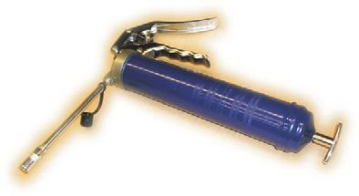
4.4 Grease guns
Figure Number Application
24981 fif
A tool with a pointed nozzle used to apply grease. Length 170 mm.
755132 Single-hand grease gun with straight discharge pipe and nozzle.
755142
Two-hand grease gun with angled discharge pipe and nozzle.

755152
Two-hand grease gun with hose and nozzle.
755146 Grease hose 450 mm. Grease hose 750 mm. Grease hose 1500 mm.

202154PM Pointed nozzle for grease guns used to apply grease in recessed nipples. Fits grease guns with hose and discharge pipe. Length 125 mm.

755140 Nozzle for neck nipples. Fits grease guns with hose and discharge pipe.
4.5 Other tools
1=163793
Service instrument for programme changes
1=155619-001
2=166161
3=166473
Both cables are included when ordering 155619001
1= Service instrument for Curtis transistor panel
2= Cable for Curtis 1243 and 1207 A
3= Cable for Curtis 1207
5- Electric drive motor – 1760
5.1 General
The drive motor is integrated with the brake and assembled together with the driving gear to form a complete drive unit.
The drive motor uses an independent excitation design. It consists of a field winding and armature winding, which are separately controlled Armature current is transferred in the conventional manner using carbon brushes (8 pcs.) lying against the armature commutator.
The rotational direction of the motor can be reversed by changing the direction of the field current.
5.2 Mechanical design
The motor consists of a housing, in which the stator windings are permanently fixed.
In the bearing box at one end, there is a carbon bridge holding four double, spring-loaded carbon brushes, constituting the motor's commutator end. The carbon brushes rest against the rotor commutator and as such are responsible for feeding rotor current to the rotor windings.
One bearing of the rotor is mounted on the bearing plate at the commutator end.
The rotor bearing at the motor drive end is designed to allow mounting of the bearing on a guide, which, together with the bearing, is pressed onto the rotor axle. The rotor axle is centred following final assembly of the guide in the driving gear housing.
All motor windings are accessible via external connections.
Electric drive motor – 1760
Disassembly of the motor from the truck
T-codeValid from serial numberDateOrder number 787, 788931876-2006-04-10232370-040
5.3 Disassembly of the motor from the truck
•Switch off the truck and disconnect the battery connector.
•Remover the motor compartment cover.
•Disconnect the motor cables (A).
•Disassemble the brake (B).
•Unscrew the five screws holding the motor shield against the motor plate (C).
A B C
•Lift out the motor and place it on a clean surface. Cover the driving gear opening.
It is now possible to commence with the necessary service and repairs of the motor.
5.4 Assembly of the motor in the truck
•Assembly is done in reverse.
•Place a new O-ring on the sealing flange (25) on the drive axle.
•Carefully lower the motor onto the driving gear while making sure the seals and gear wheels are not damaged.
•Tighten the five screws holding the motor shield in place against the motor plate to a torque of 45 Nm.
•Connect the motor cables. Verify that the polarity is correct. Connect the brake.
•Verify brake operation.