14 minute read
Fork carriage – 7420


Dismounting of the mast carriage.
13.2 Dismounting of the mast carriage.
•Dismount security split pin position 11 and both chain bolt nuts postion 12.
•Dismount washer postions 13.
•Remove the complete chain position 14.
•Remove the end plates on top of both mast beams. Take the mastcarriage out of the mast at the upper side by using a crane. CAUTION!
Take care of save load handling.
Mounting is done in reverse.
13.3 Adjusting the play
•Adjust the play with screw (15).
13.4 Roller replacement
•See also earlier drawing.
•Remove the locking ring position (16) and remove the roller (17). Assembly is done in reverse.
Fork carriage – 7420
Dismounting of the initial fork carriage.
13.5 Dismounting of the initial
fork carriage.
•Dismount the forks.
•Dismount security split pen postions 11 and both chain bold nuts position 12.
•Remove washer position 13.
•Remove chain position 14.
•Take the fork carriage out of the mast at the under side by using a crane.
CAUTION! Take care of safe load handling.
14- TruckCom
User manual for trucks using the “PowerDrive” platform. This manual is valid for version 3.5 of TruckCom p/n 182147-008.
14.1 General
TruckCom is a communication program which communicates with trucks equipped with CAN (Controller Area Network) communication. It enables the following tasks to be performed:
•Downloading truck control software.
•Viewing and adjusting operator / truck parameters and hour meters. Additionally, the truck’s parameter set (including hour meter values) can be saved to file and reloaded later.
•Viewing diagnostic data for various digital inputs/outputs and analogue data including voltages, currents and certain temperatures. The program is a Windows program running under Windows® 95/98, Windows® XP/2000 and Windows® NT.
14.2 Connection
A CAN interface of the CPC-PP type is needed to connect it to the truck, with attendant cable. Connect the interface via the printer port on a PC. Connect the cable between the interface and the truck's CAN terminal.
The CAN interface is supplied with power from the truck electronics and is protected from any high voltages in the truck if a fault should occur.
14.3 Layout
14.3.1 Main program screen
The Main window opens when the program is started. This shows the menu bar, tool buttons, workspace, log window and status window.
14.3.2 Nodes
Devices which are connected to and communicate via the CAN interface are called nodes. The nodes detected on the bus are shown in the node window. The current node status and input component/information is shown with different icons.
14.3.3 Icons
Icon Description
Node OK is shown when contact is made with a node and no errors have been reported.
Node not connected is shown when there is no contact with a node in the network.
Node not OK is shown when an error has been reported by a node. Click on node to obtain more information.
Program version is shown when information is available on which software is installed. Click to obtain more information.
Information is shown when a node has information on, for example, error codes.
Truck report
See “14.7 Truck report function” on page 7
Parameters is shown when a node has information on a parameter.
Diagnostics
Exit
14.3.4 Tool buttons and menu bar
The tool button bar allows direct access to the program’s most common functions. The menu bar allows access to all the program functions. Explanations of each menu bar item are given in the relevant section.
Search for units Disconnect from PC Download Truck report
Parameters Diagnostics Information Exit Fig. 15 Tool button bar
14.3.5 Information window
The right section of the main window contains a status window where different messages are shown.To see previous messages, use the scroll arrows in the right margin.
14.3.6 Status bar
There is a status bar at the bottom of the main window, which shows variable status when the program is run.
The following are shown from the left: Help text "pop-up" via the mouse cursor, connected/not connected to network, truck type connected, initiation result of CAN interface and the present time.
14.4 Connection function
To connect the PC the network, select the Scan units function. This can be done with the menu <Nodes | Scan units> or with the tool button [Scan nodes]
This should also be done when the truck is supplied with voltage and in normal drive mode.The program will now run a check and installation of the CAN interface. A diagnosis will also be carried out to check which units are connected in the system. The result of this diagnosis is shown in the Node window.
14.5 Disconnection function
Select the Disconnect function to disconnect from the network. This can be done with the menu <Nodes | Set PC off-Line> or with the tool button [Set PC off-Line].
The CAN interface is then reset and the CAN cable can be disconnected if so required. This enables connection to another truck without having to close the program.
14.6 Downloading program function
To download a new program to one of the nodes, select the Download software function. This can be done with the menu <Tools | Download software... > or with the tool button [Download]

14.6.1 Normal downloading (truck with key)
Select Open.. to open the file to be downloaded into a node. The file name, file type and version number are shown in the window for file information. If it is file for a controller, indicate which type of controller is to receive the file. Start downloading by selecting Start... and by restarting the truck by turning the key off and on twice. Restart must be made within 20 seconds from when the Start button has been activated.
Close the download window when the download is ready, and then disconnect the PC from the network. A new connection can now be made to verify the new program.
14.6.2 Normal downloading (truck with keypad)
Select Open to open the file to be downloaded into a node. The file name, file type and version number are shown in the file information dialogue box. If it is file for a controller, indicate which type of controller is to receive the file. Start downloading by depressing and then releasing the red key on the keypad.
The truck must be restarted within 20 seconds from when the Start key has been activated.
When downloading has been completed, close the download dialogue box and then disconnect the PC from the network. It is now possible to reconnect to verify the new application.
14.6.3 Emergency downloading (truck with keypad)
•Disconnect the battery connector.
•Select OK in the dialogue box.
•Keep the red key on the keypad depressed while reconnecting the battery connector.
•Release the red key to commence downloading.
14.6.4 Emergency downloading (truck with keypad)
E141 will be shown in the truck’s display when starting, if for any reason there is no program in the electronics card (interrupted downloading). Communication with the truck via the PC will then be minimised. Use “E141” to download the program in the card.
On some trucks, a counter, which continuously counts up, is displayed.
14.6.5 Downloading in old versions of logic card
To download to older versions of electronic cards which do not support restart with key, the button Old card... should be used instead of Start... Downloading is carried out in the same way, except that restart is done by using the battery lug instead of the key.
NOTE!
Once programmed, the logic cards in some trucks can only be upgraded with the same basic firmware. In other words, it is not possible to replace the basic firmware (other machine type).
14.7 Truck report function
It is possible to generate a report to a file or disk with the truck’s configuration and status. Select menu <Tools | Generate truck report...> or with the tool button Truck report. Save the report in Report.file.

Example of information generated in the truck report:
[GENERAL]
REPORT DATE-TIME=2004-01-19 11:11:58
CPC-PP SERIAL No=8002041
MACHINE NUMBER=555555
CUSTOMER=CUSTOMER 1
TECHNICIAN=NONAME
[CAN NODES]
MAIN CARD=0
CURTIS DRIVE CONTROLLER=16
[MAIN CARD CONFIGURATION]
SOFTWARE=181179-001
HARDWARE=167833-004
SERIAL NO=53676
[DRIVE CONTROLLER CONFIGURATION]
SOFTWARE=5
DRIVE CURRENT LIMIT (A)=300
FIELD MAXIMUM (A)=34
SERIAL NO=52857
MFG Date:=26/05/03
HOUR METERS]
A IGNITION TIME=81
B TOTAL MOVEMENT=7
C DRIVE MOTOR TIME=7
D PUMP MOTOR TIME=0
S SERVICE TIME=7
The contents of certain rows can vary according to truck type.
14.8 Parameters function
To change the truck parameters, select the Parameter function. This can be done with the menu <Tools | Change parameters > or with the tool button Parameters.
NOTE!
The truck must in Normal mode (i.e. not Parameter mode) when connecting TruckCom. Otherwise TruckCom will report “Unable to determine truck brand”
The parameter numbers follow the description in the respective truck Service Manuals, section 5000.
The parameter window shows the information and the current settings for all parameters. The parameters are divided into 4 tabs.
•[Driver] - Driver; driver parameters and PIN code storing
•[Truck] - Truck; service parameters
•[Time] - Time; time-related service parameters
•[Option parameters] - Option parameters. (no. 15 to 19)
WARNING!
Do not attempt to make any adjustments to the option parameters unless you have sufficient knowledge of the truck’s options/ modified functions. Specially modified trucks may require that you have access to special service information.
Improper adjustment of the option service parameters may result in a malfunction.
14.9 Diagnostics function
To access diagnostics, select the Diagnostic function. This can be done with the menu <Tools | Diagnostic...> or with the tool button Diagnostic. NOTE!
If the value “---” is shown in a field, or a “read status LED” is red, the communication has been interrupted for some reason and error data cannot be shown.
NOTE!
The tab information displayed in the diagnostics mode depends on the type of truck connected.
14.9.1 Representation of signal colours
The screen dumps shown in the following section have been modified to improve legibility in black and white print.
14.9.2 “Tiller arm” tab
Clicking on the tiller arm tab will display a dialogue showing the following:
• Speed lever -The status of the speed control and travel direction selector. The status of each individual hall element is displayed.
• Buttons -The status of the control buttons is displayed. “Sxx” refers to the switch designations as given in the circuit diagram.

• Option - Status of option buttons
• Battery - The measured battery voltage
• R14 - Shows the measured signal voltage from the lift/lower control
• R15 - Not used at present.
14.9.3 “Drive Controller” tab (transistor regulator driving)
Clicking on the Drive Controller tab will display a dialogue showing the following:
•Status of digital inputs and outputs of the transistor regulator. pin refers to the motor controller pin designations as given in the circuit diagram.
• Field PWM - The effective power output supplied to the field circuit as a percentage.
• Armature PWM - The effective power output supplied to the armature circuit as a percentage
• Field current - The current flowing in the field circuit in Amperes.
• Armature current - The current flowing in the Armature circuit in Amperes
• Raw throttle data - The received speed control signal as a percentage.

• Temperature - The temperature of the output stage of the transistor controller in degrees Celsius
• Inp pin 10 - The input voltage from the mode/pressure sensor. “digital O” indicates the digital status of the input.
• Inp pin 11 -The input voltage from the man-on platform sensor. “digital O” indicates the digital status of the input.
14.9.4 “Pump controller” tab (transistor regulator pump)
If the truck is equipped with a lift/lower transistor regulator, the Pump controller tab displays the following:
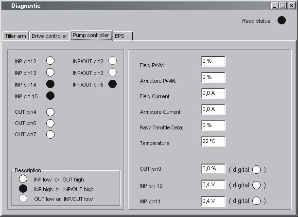
•Status of digital inputs and outputs of the transistor regulator. pin refers to the motor controller pin designations as given in the circuit diagram.
• Field PWM, Armature PWM, Field current, Armature current, Temperature - See explanation in 14.9.3
• Raw throttle data - The received lift/lower signal as a percentage.
• Out pin 9 - The output signal to the proportional lowering valve as a percentage.
• Inp pin 10 - The input voltage from the pressure sensor. “digital O” indicates the digital status of the input.
• Inp pin 11 - The input voltage from the pressure sensor. “digital O” indicates the digital status of the input.
14.9.5 “EPS” (steering servo tab)
Clicking on the “EPS” tab will display a dialogue showing the following:
“Status”
•“Operational” - Indicates the status of the servo’s control system
•“EPS enabled” - Indicates the status of the servo’s power stage output.
•“Reference switch reached” - indicates status of drive wheel in centre reference switch.

•“Reference position found” - indicates whether a successful steering in centre has been performed.
•“EPS in power save mode” - Shows whether the steering servo is in the standby mode (following a certain amount of inactivity).
“Actual values” (Measured values)
•“Temperature EPS” - The temperature of the steering servo output stage in degrees Celsius.
•“DC bus voltage” - Supply voltage to steering servo
•“Wheel position” - Shows the estimated steering angle of the drive wheel.
•“Voltage analog input 1, pin5”- The measured DC input signal (0) from the steering potentiometer.
•“Voltage analog input 2, pin13”- The measured DC input signal (1) from the steering potentiometer.
•“Current” - The measured current supplied to the steer servo motor in Ampere
•“Actual velocity” -The measured rotational speed of the steer servo motor shaft in r.p.m.
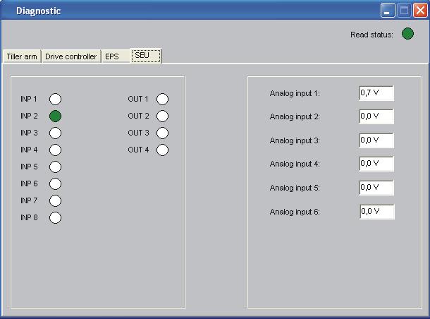
14.9.6 SEU tab (Extra I/O module)
When the truck is equiped with a Spider Extension Unit (former Extra I/ O module) the SEU tab shows following:
•“INP X” - Shows the logical status for the digital inputs.
•“OUT X” - Shows the logical status for the digital outputs.
•“Analog input X” - Shows the voltage level on the analog inputs. See chapter 5000 for more information about the SEU and how the inputs and outputs are connected.
14.10 Other menu functions
14.10.1 Save to file
The truck parameters can be saved in the PC for downloading at a later date.Select <File | Save to file | Parameters>. All parameters in the nodes which are connected to the bus will be scanned in and saved in a file.If only the hour meters are needed, select <File | Save to file | Hour meters>.
14.10.2 Download from file
A set of parameters can be downloaded from the PC to the truck. Select <File | Load from file | Parameters >. The parameters in the file will be copied to the nodes connected to the bus. If only the hour meter settings are needed, select <File | Load from file | Hour meters >.
14.10.3 Reset CAN adapter
If problems should occur when resetting the CAN adapter connected to the PC, this can normally be done manually by making sure that the adapter is supplied with voltage and then selecting <Nodes | Reset CPC-PP>.
14.10.4 Delete error code log
To delete the truck’s error code log, start the truck in parameter mode and then select <Tools | Erase error log>.
14.10.5
Reset hour meter
To reset the truck’s hour meter, start the truck in drive mode and then select <Tools | Reset hour meters >.
14.10.6
Read error code log
To show the truck’s error code log, select < Tools | Read error log >.
14.10.7
Adjust date and time
To quickly adjust the truck’s data and time, select < Tools | Adjust date & time >. The time given in the PC will now be downloaded into the truck.
NOTE! This does not apply to trucks without a real-time clock.
14.10.8 Adjusting the hour meter on older cards
To adjust the hour meter on trucks with older cards, select <Tools | Adjust Hour meters>. The time given in the PC will now be downloaded into the truck.
14.10.9 Help About the TruckCom application
To see program information, select <Help | About TruckCom...> or use the tool button [Information].
14.10.10
Exit
To exit the program, select <File | Exit > or use the tool button [Exit].
14.11 Specifications
Table 40: CAN interface specification
14.12 Installation
NOTE!
The program must be installed from the hard disk.
NOTE!
The software application in the computer can be damaged, which is why the PC installation should be performed by someone with the required knowledge. Toyota does not accept any responsibility for any errors that occur during the installation.
NOTE!
All references to PC operating system actions, menus and commands are based on the English language version of Windows®
14.12.1 Installation on a PC with Windows® 95/98
If a previous version of the TruckCom application has been installed on the PC, it will be necessary to edit the System.ini file.
Start the Msconfig.exe application by selecting the Start button, selecting Run and then typing msconfig.
•Click on System.ini and open the folder (386Enh).
•Unmark the option at Device=C:\Windows\Cpcppvd.vxd.
•Save the change and close the application.
Now continue with installationThe software application is supplied on a CD or via a network. Start installation by running X:\SETUP.EXE, where X:\ is the drive on which the installation application can be found.Then follow the on-screen instructions.
14.12.2 Installation on a PC with Windows XP/ 2000
To make the application work, it is necessary to enter a value in the Windows® Registry and then make a few alterations in the Windows® Control panel.
Due to the built-in Windows® security, this must be done manually.
The instructions below provide step-by-step guidance to enable these changes and make the interface operate under Windows XP and Windows 2000.The changes can be made either before or after TruckCom is installed.
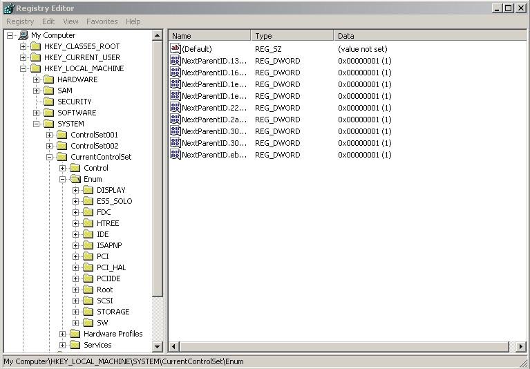
•Open the Registry Editor. To do this, select the Start button, then Run, type regedit and press Enter.
•Mark the Enum folder which can be found under HKEY_LOCAL_MACHINE\SYSTEM\CurrentControlSet inside the Registry Editor.
•Select the Edit option, then Find and type PortName to search for the correct folder.
NOTE! The location of the folder differs between different computers (some may be \Enum\Root\.., while others could be \Enum\ACPI\ etc.). Thus be sure to search for the correct folder.
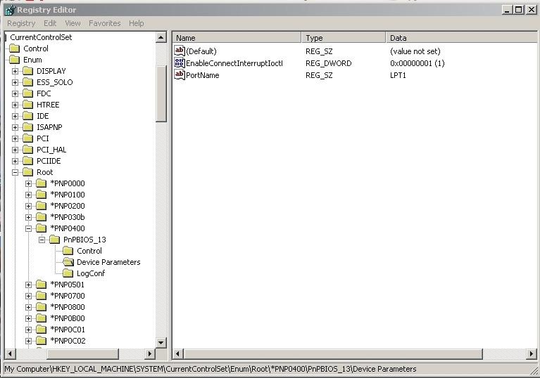
When the folder is found, check that LPTx (x=1, 2, 3, 4) is displayed in the PortName data field and that the folder name is Device Parameters.

•Right-click with the mouse in the right box to enter a new value of the DWORD type and with the name
.
•Change the value in data field 1 by right-clicking on the name and selecting Modify.
The Device Parameters folder should look like the one in the picture.

The Registry change is now complete. Close the Registry Editor.
Changes in Windows® control panel
•Select the Start button.
•Choose Settings, then Control Panel and double-click on System.
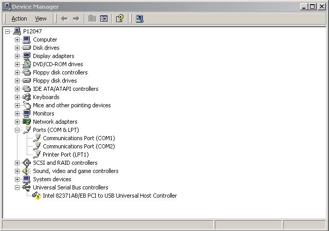
•Select Hardware.
•Click on Device Manager and open Ports (Com & LPT).
•Double-click on the LPT port to be changed.
•Select the Port Settings tab and select the "Use any Interrupt assigned to the port" option and click OK.

The software application is supplied on a CD or via a network. Start installation by running X:\SETUP.EXE, where X:\ is the drive on which the installation application can be found. Then follow the on-screen instructions.

14.12.3 Installation on a PC with Windows NT
The software application is supplied on a CD or via a network. Start installation by running X:\SETUP.EXE, where X:\ is the drive on which the installation application can be found. Then follow the on-screen instructions.
14.12.4 In case of communication problems with CAN
Make sure the computer settings for the printer port in the BIOS Setup are as follows:
Port address:0378
IRQ:7
Mode:Output only
For detailed information on how to change the Setup settings, refer to the User's Guide supplied with the computer.
14.12.5
To uninstall
To uninstall TruckCom under Windows®:
•Select the Start button, Settings, Control Panel, Add/Remove Programs.
•Then select the TruckCom Program and click Change/Remove.
15- Destruction instructions
15.1 General
These instructions have been drawn up as part of Toyota's environmental management program. An important motive is, by taking nature into consideration, to economize with resources. In other words, you should try to recycle material as far as possible. This is to minimise the discharge of environmentally-hazardous substances.
The dismantling instructions are designed for an F-code (truck family) and then divided into different C-codes (parts and functions on the truck.) These C-codes are:
•0000 Chassis
•1000 Motors
•2000 Transmission/drive transmission
•3000 Brakes/belt/wheel system
•4000 Steering system
•5000 Electrical system
•6000 Hydraulics/pneumatics
•7000 Working function - lift frame
•8000 Auxiliary/installation equipment
•9000 Accessories/extra equipment
The instructions do not tell you the type of material the parts are made of, but refer you to different material containers where the parts should be collected. Some plastics are marked, which means some instructions refer to the marking to determine the collection container to use.
15.2 Procedure
When sorting a component part you must know what plastic parts, liquids, environmentally hazardous substances and metals it incorporates.